Unlock instant, AI-driven research and patent intelligence for your innovation.

Magnetic field correcting method, megnetic field generating equipment and magnetic resonance imaging equipment

A technology for magnetic resonance imaging and production equipment, which can be used in magnetic resonance measurement, material analysis through resonance, electromagnets, etc., and can solve problems such as poor calibration efficiency.

Inactive Publication Date: 2004-04-07
GE MEDICAL SYST GLOBAL TECH CO LLC
View PDF0 Cites 7 Cited by
  • Summary
  • Abstract
  • Description
  • Claims
  • Application Information

AI Technical Summary

Problems solved by technology

Therefore, the correction efficiency is poor considering the power delivered to the two pairs of annular loop coils

Method used


Image

  • Magnetic field correcting method, megnetic field generating equipment and magnetic resonance imaging equipment
  • Magnetic field correcting method, megnetic field generating equipment and magnetic resonance imaging equipment
  • Magnetic field correcting method, megnetic field generating equipment and magnetic resonance imaging equipment

Examples


Embodiment Construction

[0023] Detailed Description of Preferred Embodiments

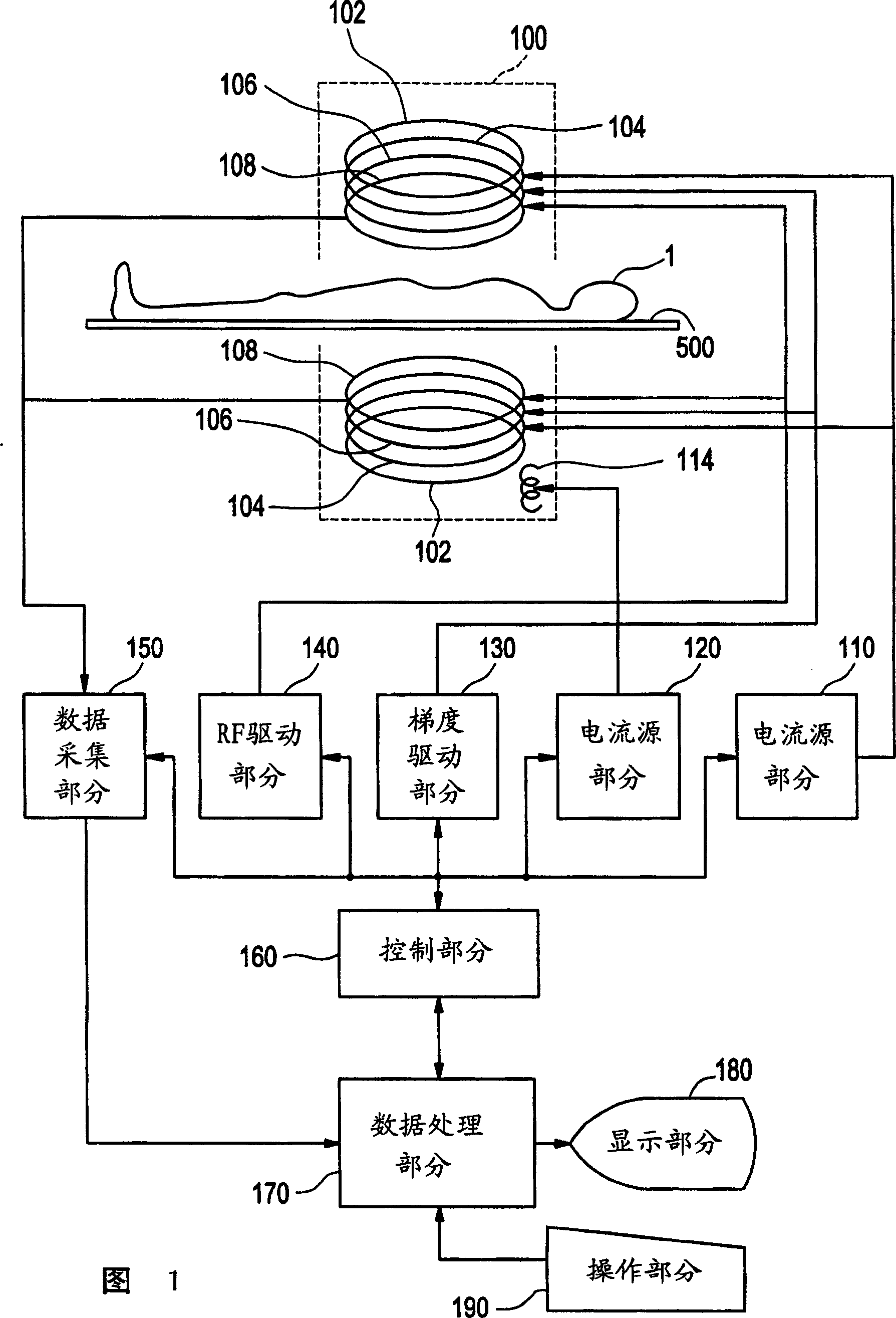
[0024] Embodiments of the present invention will now be described in detail with reference to the accompanying drawings. Accompanying drawing 1 shows the block diagram of magnetic resonance imaging equipment. This device is an embodiment of the invention. The structure of the device represents an embodiment of a magnetic resonance imaging device according to the invention.

[0025] The device has a magnet system 100 as shown in FIG. 1 . The magnet system 100 has a main field magnet portion 102 , a correction coil portion 104 , a gradient coil portion 106 , an RF coil portion 108 and a compensation coil portion 114 . The object to be imaged lies on the table 500 and is transported into and out of the inner space (bore) of the magnet system 100 .

[0026] The main field magnet portion 102, the correction coil portion 104, the gradient coil portion 106, and the RF coil portion 108 each include a pair of members spatially ...


PUM


Abstract

For the purpose of efficiently correcting a quadratic term component of a static magnetic field, when an inhomogeneity error of a static magnetic field generated by a pair of magnets (102) supported by yokes (202, 204) so that the magnets face each other across a space is to be corrected, a quadratic term component of the static magnetic field is corrected by a quadratic term component of a magnetic field generated by a pair of circular loop coils (104), and a zero-th order term component of the magnetic field from the pair of circular loop coils is compensated by a zero-th order term component of a magnetic field generated by coils (114) wound around the yokes (204).

Description

technical field [0001] The present invention relates to a magnetic field correction method, a magnetic field correction device, and a magnetic resonance imaging device, and more particularly to a method of correcting an inhomogeneity error of a static magnetic field generated by a pair of magnets supported by a yoke so that the magnets spatially face each other Method, device for generating a stationary magnetic field corrected for inhomogeneity errors, and magnetic resonance imaging device including such a magnetic field generating device. Background technique [0002] In a conventional device that generates a uniform static magnetic field in space by a pair of magnets facing each other, the quadratic component of the magnetic field generated by the pair of loop loop coils using two pairs of loop coils arranged symmetrically with respect to the center of the static magnetic field space Eliminates (corrects) the quadratic component of the stationary magnetic field. The magn...

Claims


Application Information

Patent Timeline
IPC IPC(8): A61B5/055G01R33/383G01R33/3875H01F7/20
CPCG01R33/3875A61B5/055
Inventor 后藤隆男
Owner GE MEDICAL SYST GLOBAL TECH CO LLC
Features
  • R&D
  • Intellectual Property
  • Life Sciences
  • Materials
  • Tech Scout
  • Unparalleled Data Quality
  • Higher Quality Content
  • 60% Fewer Hallucinations
Learn More