Full optical fiber current measuring method

A current test, all-fiber technology, applied in the field of all-fiber current test, can solve the problems of large influence of temperature, instability of optical polarization state, etc., to eliminate the influence of the system, ensure the test accuracy, and enhance the effect of commercial development

Inactive Publication Date: 2004-04-14
FUDAN UNIV
View PDF0 Cites 5 Cited by
  • Summary
  • Abstract
  • Description
  • Claims
  • Application Information

AI Technical Summary

Problems solved by technology

Due to the large temperature influence of the Faraday effect and the instability of the polarization state of light itself, there are many deficiencies in the truly practical high-current sensing test system

Method used


Image

  • Full optical fiber current measuring method
  • Full optical fiber current measuring method
  • Full optical fiber current measuring method

Examples


Embodiment Construction

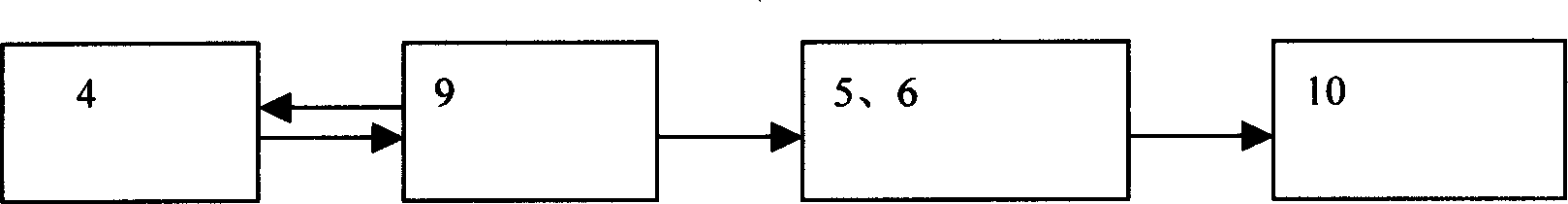
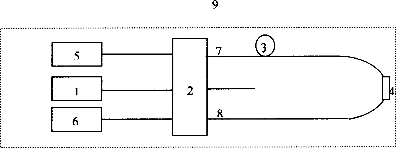
[0045] To verify the proposed current test method, experimental tests were carried out with an AC current with a maximum peak value of 6.6 amperes and a frequency of 50 Hz. The specific experimental structure diagram is as follows: figure 1 As shown, the light emitted by the laser (1) enters the fiber coupler (2) through a jumper connection, and after being split, one path of light passes through the fiber delay line (3) from the coupler (7) to the sensor probe (4 ), and finally return to the end of the optical fiber (8); another beam of light is from the end of the coupler (8), passes through the sensing head (4), reaches the fiber delay line (3), returns to the end of the fiber coupler (7), and interferes After the signal is received by the photoelectric detector (5) (6), an electrical signal is obtained. The electrical signal is amplified by an amplifier circuit, collected by a data acquisition card, and subjected to data processing to obtain a current signal.

[0046] In ...


PUM

PropertyMeasurementUnit
Wavelengthaaaaaaaaaa

Abstract

Using characteristic of close relation between optical path change of coherent beam formed by a sensor header and current to be measured, the invention through phase relation of interference signals realizes the function for measuring current. Highlighted advantages of the invention are as follows. There is no limit of linear working space of system. Measuring sensitivity is adjustable based on physical circumstances so as to ensure measuring accuracy at both of large current and small current. The method of measuring current is based on optical path change of magnetic interference instead of existing technology depending on Faraday rotation effect, providing features of simple measuring system and no technical problem for controlling polarization in optical path. Comparing with prior art, the invention provides stable measuring result since its symmetrical optical path eliminates influence on the system caused by slow varying heat effect and surrounding vibration.

Description

technical field [0001] The invention is an all-fiber current testing method. Background technique [0002] Large-current testing is a long-term concern in the power industry system. Because the traditional current testing system weighs tons, has a large volume, and is difficult to install and debug, there are many problems in practical applications. With the improvement of optical fiber technology and the maturity of devices, the use of optical fiber to realize the test of high current is a problem that people have paid close attention to, and some progress has been made in recent years. Most of its test principles use the Faraday effect that the current changes the polarization state of light. Due to the large temperature influence of the Faraday effect and the instability of the polarization state of light itself, there are many deficiencies in a truly practical high-current sensing test system. Contents of the invention [0003] The object of the present invention is ...

Claims


Application Information

Patent Timeline
IPC IPC(8): G01R15/24
Inventor 贾波
Owner FUDAN UNIV
Why Eureka
Try Eureka