Arrangement for fixing engine with front air cooling of passenger car in middle position

An air intake cooling and engine technology, applied in air cooling, engine components, engine cooling, etc., can solve problems such as engine mid-position

Inactive Publication Date: 2004-04-21
ZHENGZHOU YUTONG BUS CO LTD
View PDF0 Cites 8 Cited by
  • Summary
  • Abstract
  • Description
  • Claims
  • Application Information

AI Technical Summary

Problems solved by technology

[0004] The purpose of the present invention is to provide a mid-engine method for air inta...

Method used


Image

  • Arrangement for fixing engine with front air cooling of passenger car in middle position
  • Arrangement for fixing engine with front air cooling of passenger car in middle position
  • Arrangement for fixing engine with front air cooling of passenger car in middle position

Examples


Embodiment Construction

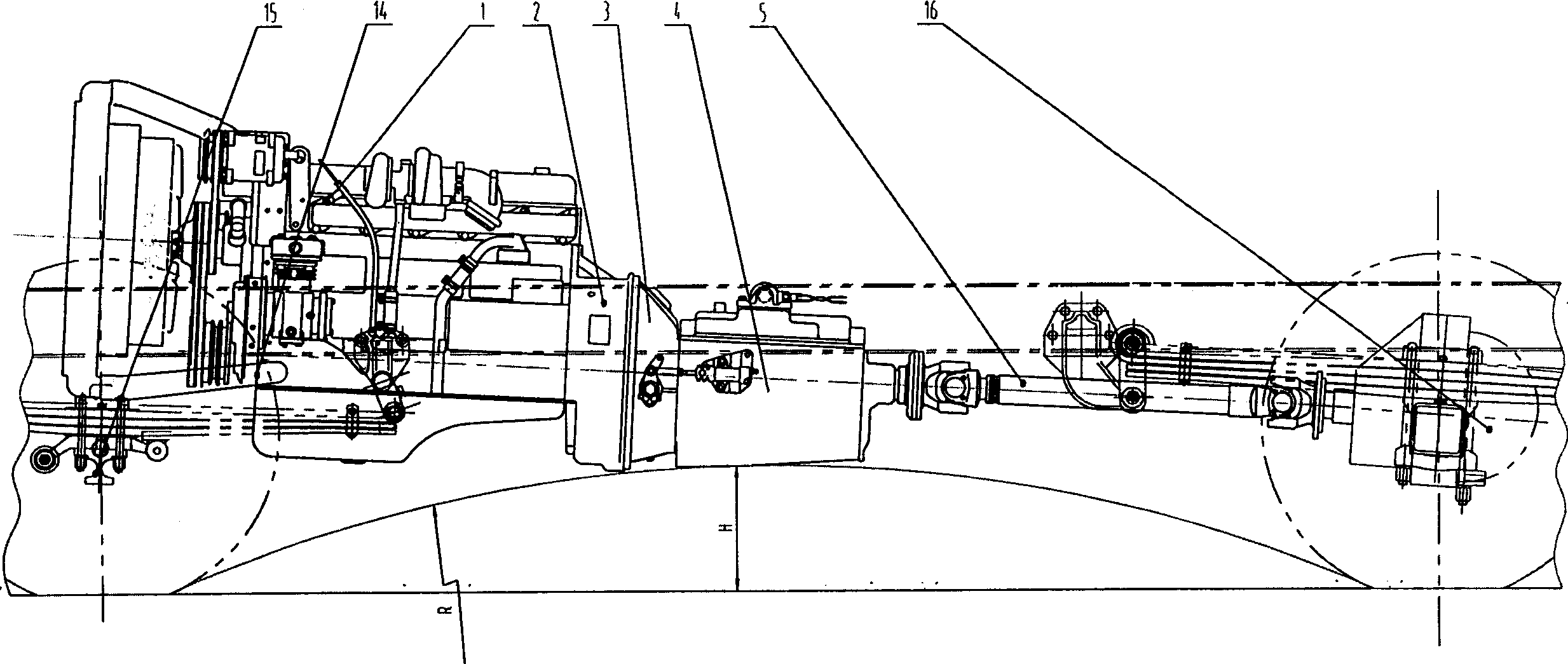
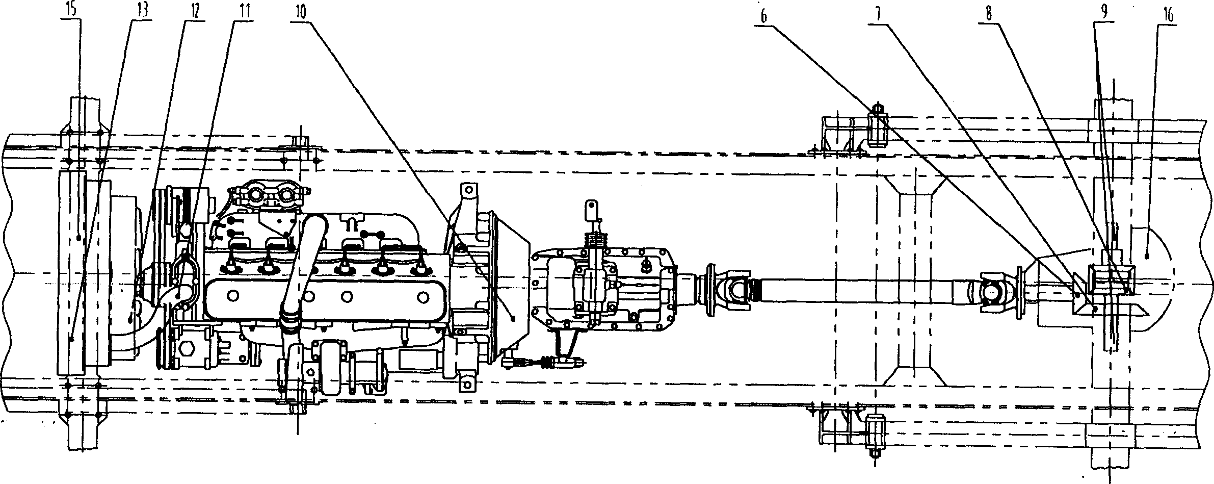
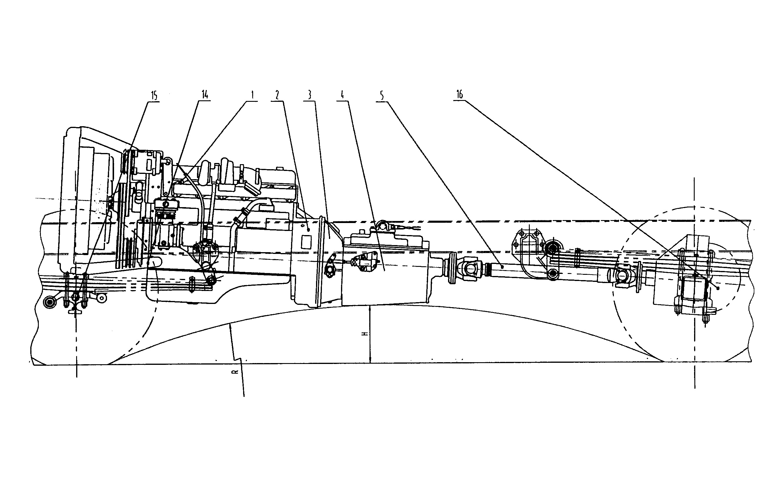
[0012] Such as figure 1 , figure 2 As shown, the engine mid-installation method of the air intake cooling at the front of the passenger car of the present invention is to move the traditional front engine 1 behind the front axle 15, and to reduce the installation height, and the engine 1 is installed with bolts on the rear end surface of the flywheel housing 2. Connected with the clutch housing 3 installed on the front end of the gearbox 4, the power of the engine 1 is transmitted to the transmission shaft 5 through the clutch 10 through the output shaft of the gearbox 4, and then input to the rear axle driving gear 6 and the passive gear through the rear axle input flange. The gear 7 is transmitted to the rear axle wheels through the differential 8 and the half shaft 9. The engine 1, the clutch 10 and the gearbox 4 together form a powertrain assembly, the front suspension brackets located on the left and right sides of the front end of the engine block, and the rear suspens...


PUM


Abstract

A method for arranging the engine at the position behind the middle bridge of coach and using the front air inflow to cool the engine is disclosed. The engine is connected to the shell of clutch. The power of engine is transmitted to the drive shaft via clutch and the output shaft of speed variator and in turn to the wheels on back bridge via input flange, drive gear, driven gear, differential gear and semi-axle. Its advantages are flat floor, low noise and easy maintenance.

Description

technical field [0001] The invention relates to an engine-mounted method for air intake cooling at the front of a passenger car. Background technique [0002] How to expand the usable space inside the vehicle and meet the comfort and safety requirements of passengers on the premise of a certain vehicle external dimension is a common problem faced by domestic and foreign bus manufacturers. Central engine is undoubtedly one of the effective ways to solve this problem. [0003] The mid-engine technology in the usual sense, due to the use of some proprietary technologies and some representing the advanced technology level of the automotive industry (such as: horizontal engine, horizontal gearbox, large drop front / rear axle or front independent suspension, lateral Air intake, cooling system hydraulic drive, etc.) have a low degree of commonality with ordinary front-engine / rear-mounted buses, so the cost is expensive, and it is impossible to enter the market in large quantities a...

Claims


Application Information

Patent Timeline
IPC IPC(8): B60K5/00B60K5/12B60K17/06F01P1/06
Inventor 吴虹飞罗伟谷杰伟高欣汤吉文
Owner ZHENGZHOU YUTONG BUS CO LTD
Why Eureka
Try Eureka