Bobbin connector for spinning spindle or silk throwing spindle

A technology of spinning spindles and couplings, which is applied in textiles and papermaking, conveying filamentous materials, processing thin materials, etc., can solve problems such as complex structure and loss, and achieve the effect of simple manufacturing

Inactive Publication Date: 2004-04-21
NOVIBRA
View PDF1 Cites 14 Cited by
  • Summary
  • Abstract
  • Description
  • Claims
  • Application Information

AI Technical Summary

Problems solved by technology

However, it has the disadvantage that such a bobbin coupling requires additional components which can be lost when the spindle is in operation, and is also particularly complex in construction

Method used


Image

  • Bobbin connector for spinning spindle or silk throwing spindle
  • Bobbin connector for spinning spindle or silk throwing spindle
  • Bobbin connector for spinning spindle or silk throwing spindle

Examples


Embodiment Construction

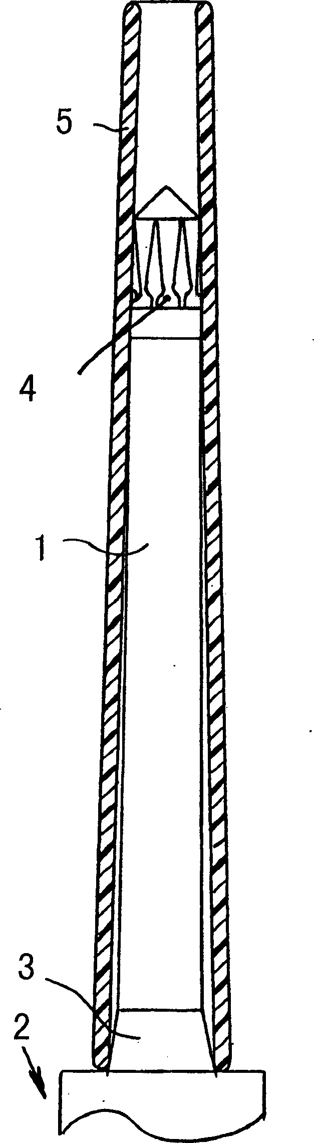
[0029] exist figure 1 A longitudinal view of the spindle top 1 of the spinning or twisting spindle 2 is shown in . In its lower part, the upper spindle part 1 merges into a conical bearing surface 3, on which a drive spindle disk (not shown) and a spindle shaft are connected in a known manner. In the upper region of the spindle upper part 1, a bobbin coupling 4 is arranged, which will be described in detail below.

[0030] A bobbin 5 , which is shown in longitudinal section, is inserted onto the spindle upper part 1 . Its underside rests on the conical bearing surface 3 or rests against a stop and is thus centered on its underside. The bobbin 5 is synchronously driven along the direction of rotation by the rotating spindle upper part 1 during the operation of the spindle 2 .

[0031] When inserting the bobbin 5 into the spindle upper part 1, usually the last 50 mm of the bobbin 5 is exposed downward. This is possible both with manual and automatic doffing. Alternatively, ...


PUM


Abstract

The winder tube coupling for a spinning or twisting spindle is so structured that gripping of a winder tube with an upper part of the spindle is realized by a joining part of a positive motion coupling composed of (two or more) recessed parts and (two or more) protrusions. The recessed parts are arranged on the upper part of the spindle and formed into vertical channels, and the protrusions are arranged on the winder tube and formed into cylindrical pegs, so that the pegs are engaged with the vertical channels. While the spindle is operating, the pegs are arranged in the direction of the top of the spindle on stopping surfaces where the vertical channels are made to be narrowed. A cap having the vertical channels is preferably mounted on the upper part of the spindle.

Description

technical field [0001] The invention relates to a bobbin coupling for spinning or twisting spindles, wherein the synchronous driving of the bobbin on the upper part of the spindle is realized by a form connection comprising dimples and protrusions. Background technique [0002] It is known that the bobbins are centered and simultaneously driven synchronously by elastic elements. It is also known that the centering and synchronizing of the bobbin tubes takes place under the action of centrifugal force via coupling elements. In both variants, either a non-positive connection or a form-fit connection of the tube coupling can be produced, and optionally also a non-positive connection and a positive connection at the same time. However, it has the disadvantage that such a bobbin coupling requires additional components which can be lost during spindle operation and, besides, is of a particularly complex construction. [0003] A form-fitting tube coupling of the type mentioned at...

Claims


Application Information

Patent Timeline
Patent Type & Authority Applications(China)
IPC IPC(8): B65H54/54B65H49/06B65H75/10B65H75/26B65H75/30D01H7/16
CPCB65H75/30B65H49/06D01H7/16B65H2701/31
Inventor G・施塔莱克G・谢夫勒
Owner NOVIBRA
Why Eureka
Try Eureka