Mosaic ceramic tile unit vibrating binder

A technology of inlaying ceramic tiles and pasting devices, which is applied in the direction of architecture and building construction, and can solve problems such as uneven pressure

Inactive Publication Date: 2004-04-21
新优有限公司
View PDF1 Cites 2 Cited by
  • Summary
  • Abstract
  • Description
  • Claims
  • Application Information

AI Technical Summary

Problems solved by technology

However, if the ball pressing the mosaic tile unit is too large, the pressure will become uneven, and it will be smaller than the

Method used


Image

  • Mosaic ceramic tile unit vibrating binder
  • Mosaic ceramic tile unit vibrating binder
  • Mosaic ceramic tile unit vibrating binder

Examples


Embodiment Construction

[0017] Embodiments of the present invention will be described in further detail below with reference to the accompanying drawings.

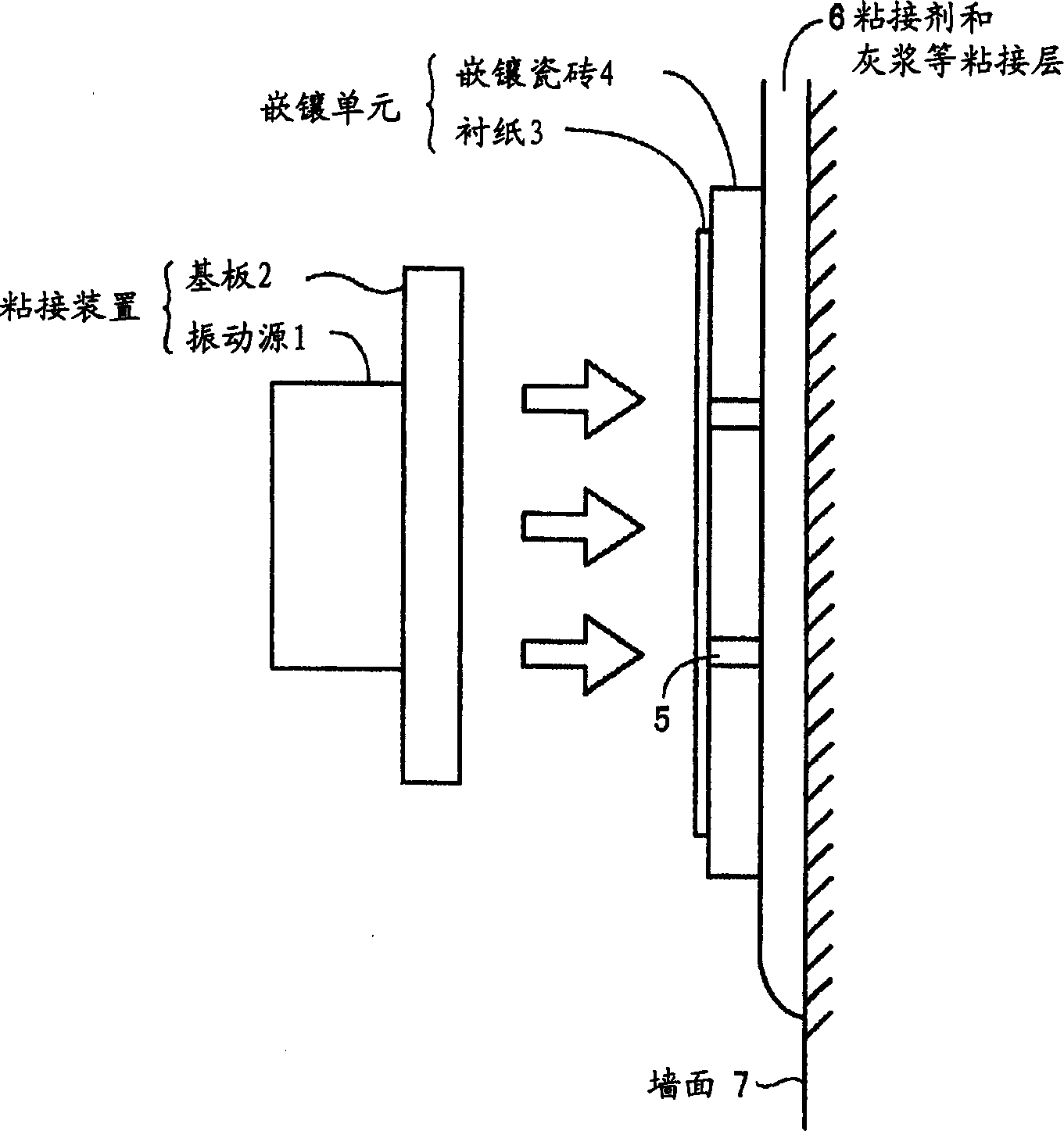
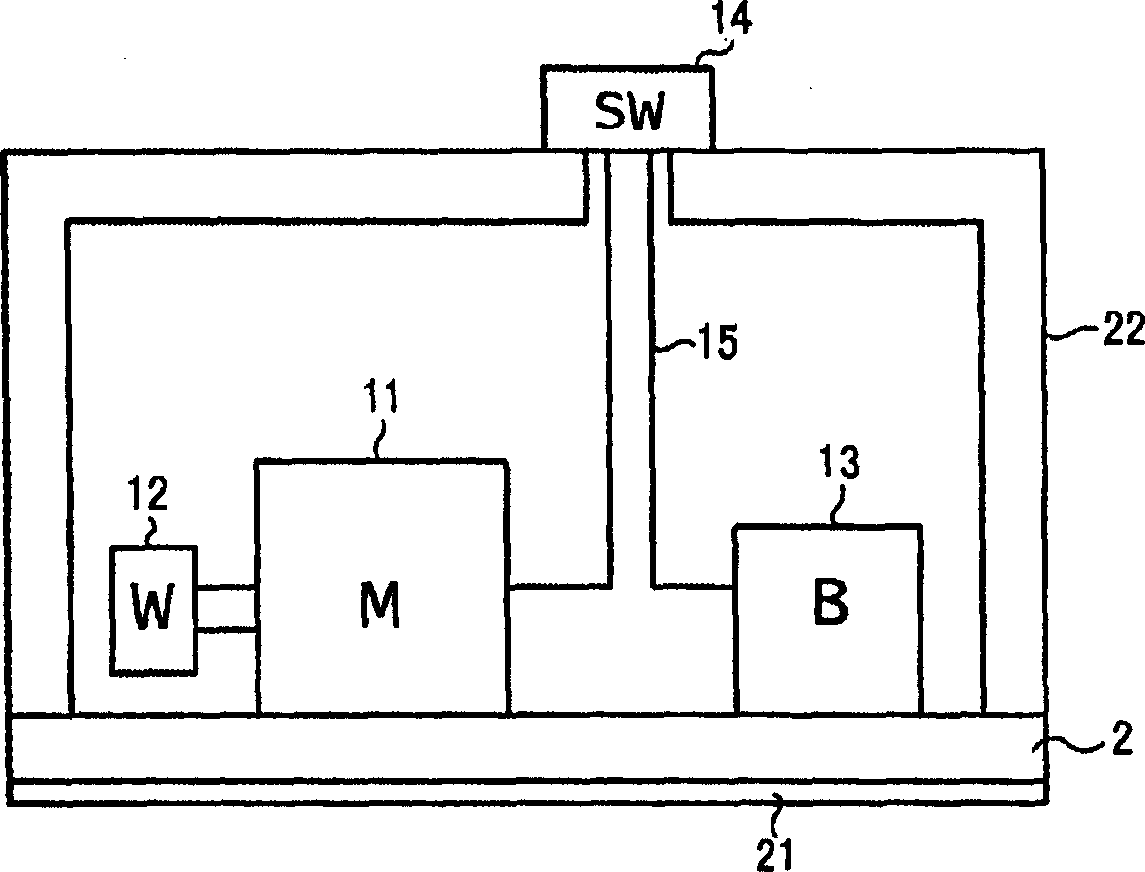
[0018] figure 1 It is a schematic cut-away view of the mosaic tile unit vibration pasting device of the present invention, schematically describing the situation in which the mosaic tile unit is pasted on the wall (including the floor surface etc.) 7 . The vibrating pasting device is composed of a vibration source 1 and a substrate 2 on which the vibration source 1 is installed. The mechanical vibration of the vibration source 1 is transmitted to the substrate 2 in contact with the vibration source 1 . Vibration source 1 can be battery internal power supply type, also can be the external power supply type that is powered by the external power supply outside the vibration sticking device, because battery, switch, wiring etc. are all very simple, so not shown in the figure.

[0019] Hold this vibrating pasting device (the device cover is not show...


PUM


Abstract

A vibration sticking machine for sticking the inlaid ceramic tile unit onto the surface of wall or floor features that under the action of vibration source, its base plate can generate mechancial vibration and transfer the vibration force to said inlaid ceramic tile unit in order to stick it via adhesive layer onto the wall (or floor) surface. Said inlaid ceramic tile unit is composed of several inlaid ceramic tiles and a lining paper which can be removed. Its advantage is uniform pressure.

Description

technical field [0001] The present invention relates to a vibrating pasting device for mosaic tile units, in particular to a so-called mosaic sticker unit that combines multiple mosaic tiles with backing paper, or glues mosaic tiles piece by piece with resin without backing paper, A so-called back-bonded mosaic tile unit that sticks the side with resin on the wall or the like, and sticks it to the wall or floor with mortar or the like with uniform pressure. Background technique [0002] As disclosed in JP-A-7-127220, in the past, in order to attach mosaic tiles to walls or floors, the mosaic tiles had to be pasted piece by piece, which was time-consuming and cumbersome, so the mosaic sticker unit or However, these mosaic tile units have disadvantages such as poor overall shape maintenance and difficult pasting work. Therefore, the invention disclosed in the above-mentioned gazette adopts a mosaic tile unit having joint grooves, and the joint grooves can be simply peeled off...

Claims


Application Information

Patent Timeline
IPC IPC(8): E04F21/18
Inventor 森清一
Owner 新优有限公司
Why Eureka
Try Eureka