Manufacturing method of polarizer

A manufacturing method and polarizer technology, which is applied in the field of polarizer manufacturing, can solve problems such as peeling off of protective film and degradation of polarization performance, and achieve the effects of suppressing decurling, excellent optical properties and adhesive strength

Active Publication Date: 2016-12-28
SUMITOMO CHEM CO LTD
View PDF10 Cites 0 Cited by
  • Summary
  • Abstract
  • Description
  • Claims
  • Application Information

AI Technical Summary

Problems solved by technology

However, when a polarizing plate in which a protective film is laminated on a polarizing film via a water-soluble adhesive is used for a long period of time under humid and hot conditions, there is a problem that the polarizing performance decreases and the protective film is peeled off from the polarizing film.

Method used


Image

  • Manufacturing method of polarizer
  • Manufacturing method of polarizer
  • Manufacturing method of polarizer

Examples


no. 2 Embodiment approach

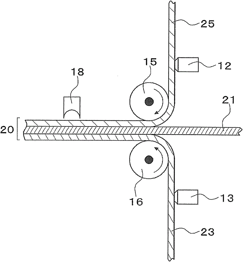
[0061] In the present embodiment, the acrylic resin film 25 is pasted so that the ratio of the pre-sticking tension per unit cross-sectional area of ​​the acrylic resin film 25 to the pre-sticking tension per unit cross-sectional area of ​​the transparent resin film 23 is 1 or more. That is, by applying a higher tension to the acrylic resin film 25 than the transparent resin film 23, a larger shrinkage stress is generated in the acrylic resin film 25, and excessive decurling is suppressed. Here, tension before sticking can be imparted by stretching the film before sticking in a direction along the transport direction of the film. Specifically, for example, a winding roll (not shown) that winds the polarizing plate 20 in a roll shape has a greater winding force than a delivery roll (not shown) of the acrylic resin film 25 in the form of a delivery roll. The method of winding force makes the rotation speed of the two rollers different.

[0062] Here, the pre-sticking tension pe...

Embodiment 1

[0188] (a) Manufacture of acrylic resin film

[0189] (acrylic resin and acrylic elastic polymer particles)

[0190] Let the copolymer whose weight ratio of methyl methacrylate / methyl acrylate be 96 / 4 be an acrylic resin. In addition, it is an elastomer particle with a three-layer structure, the innermost layer contains a hard polymer that is a copolymer of methyl methacrylate and a small amount of allyl methacrylate, and the middle layer contains butyl acrylate as a main component. A soft elastomer of ester, a copolymer of styrene and a small amount of allyl methacrylate, the outermost layer consists of a hard polymer that is a copolymer of methyl methacrylate and a small amount of ethyl acrylate, Particles having an average particle diameter of 240 nm up to the elastomer as the intermediate layer were used as acrylic elastic polymer particles.

[0191] (production of acrylic resin film)

[0192] The acrylic resin and the acrylic elastic polymer particles were mixed in a w...

Embodiment 2

[0203] In (c) of Example 1, set the peripheral speed ratio R 2 / R 1 It was 1.0107, and other polarizing plates were produced in the same manner as in Example 1. The amount of curl of the obtained polarizing plate was measured by the same method as (d), and it was found that the cyclic olefin resin film side was a concave reverse curl, and the maximum value was -79.0 mm. The results are shown in Table 1.


PUM

PropertyMeasurementUnit
wavelengthaaaaaaaaaa

Abstract

Provided is a method for producing a polarizing plate. The method includes the following steps: (A) a material film delivery process, wherein a film is delivered in a way that a polarizing film is clamped by a acrylic resin film and a transparent resin film; (B) a bonding process, wherein the film is bonded through clamping of the laminated bodies of the film by a first bonding roller and a second bonding roller, the first bonding roller is used for being contacted and rotating with the acrylic resin film, and the second bonding roller is used for being contacted and rotating with the transparent resin film; and (C) a solidifying process, so that a bonding agent is solidified. During the bonding process (B), in a way that the contraction stess of the laminated bodies of the acrylic resin film is larger than that of the laminated bodies of the transparent resin film, the two films are bonded onto a polarizing plate under a condition that tension is applied to the two films.

Description

technical field [0001] The present invention relates to a method for manufacturing a polarizer, and more particularly to a method for manufacturing a polarizer in which an acrylic resin film is attached to one side of a polarizing film and a transparent resin film is attached to the other side of the polarizing film. Background technique [0002] A polarizing plate is used as a component of a liquid crystal display device, and the demand for the polarizing plate is rapidly increasing along with the spread of the liquid crystal display device. Moreover, with the application of liquid crystal display devices to large televisions, the polarizing plate is also required to be thinner and cheaper while maintaining or improving its performance. [0003] Usually, a polarizing plate is configured by affixing a transparent protective film to at least one side, usually both sides, of a polarizing film made of polyvinyl alcohol-based resin adsorbed and oriented with a dichroic dye. As ...

Claims


Application Information

Patent Timeline
Patent Type & Authority Patents(China)
IPC IPC(8): G02B5/30G02B1/14G02F1/1335B32B37/12B32B38/16B32B27/08B32B7/02B32B7/12
CPCB29D11/00644B32B27/08B32B37/12B32B38/16G02B1/14G02B5/3083G02F1/133528
Inventor 白石贵志市原正宽林秀树
Owner SUMITOMO CHEM CO LTD
Why Eureka
Try Eureka