Device for separating and recovering cooling liquid in cutting machine tool and grinder

A technology of cutting machine tools and recovery devices, which is applied in the field of separation and recovery devices for coolant in cutting machine tools and grinding machines

Inactive Publication Date: 2004-04-28
ZETA HEIWA
View PDF1 Cites 6 Cited by
  • Summary
  • Abstract
  • Description
  • Claims
  • Application Information

AI Technical Summary

Problems solved by technology

[0004] However, in conventional metalworking machine tools, the coolant injected directly into this transient region (tool contact area) through a nozzle is thrown off due to the rotation of the tool or workpiece, and can only superficially slide along the surface of the tool and workpiece. However, it is difficult to say that the coolant is effective in cooling and lubricating

Method used


Image

  • Device for separating and recovering cooling liquid in cutting machine tool and grinder
  • Device for separating and recovering cooling liquid in cutting machine tool and grinder
  • Device for separating and recovering cooling liquid in cutting machine tool and grinder

Examples


Embodiment Construction

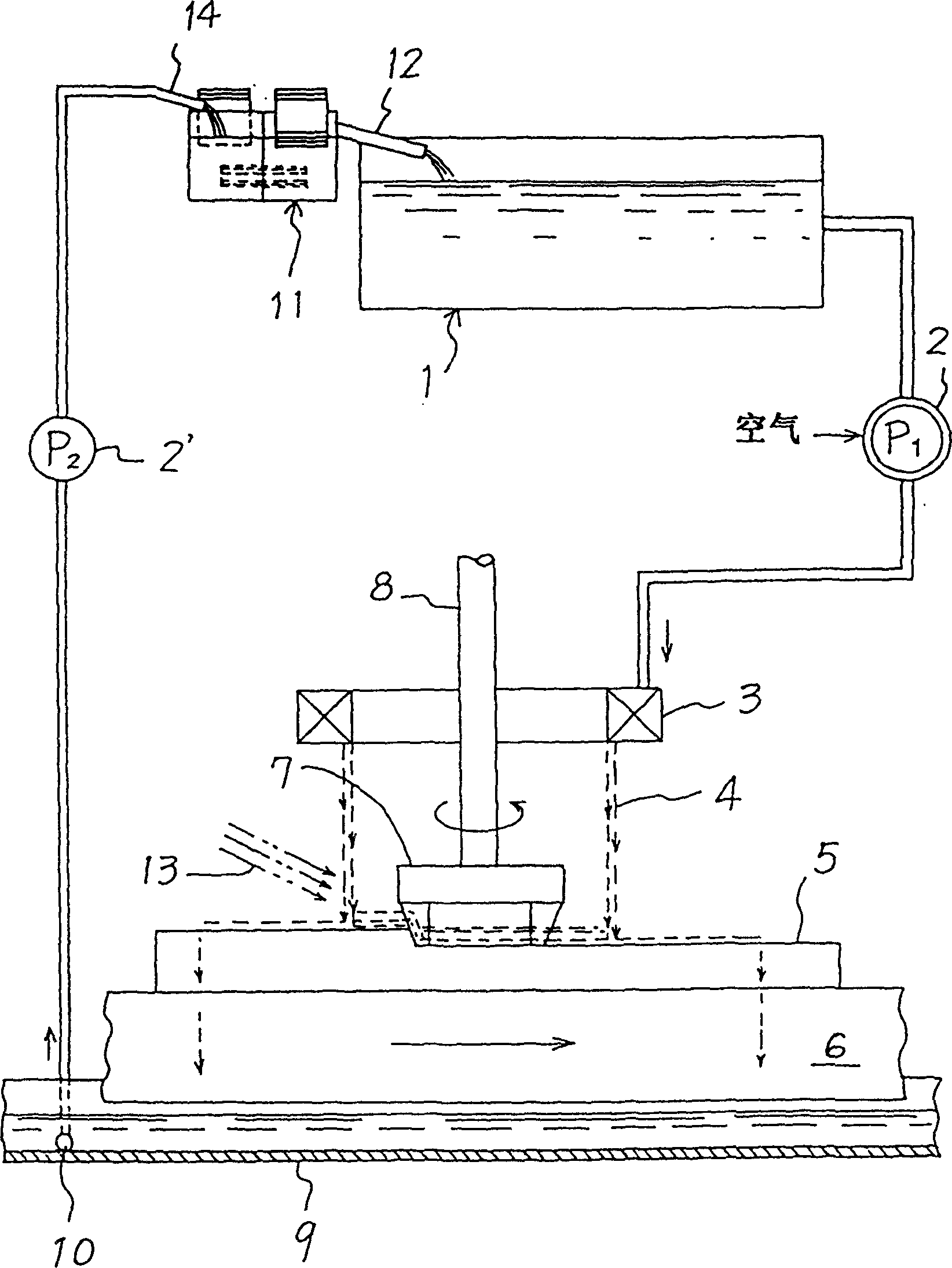
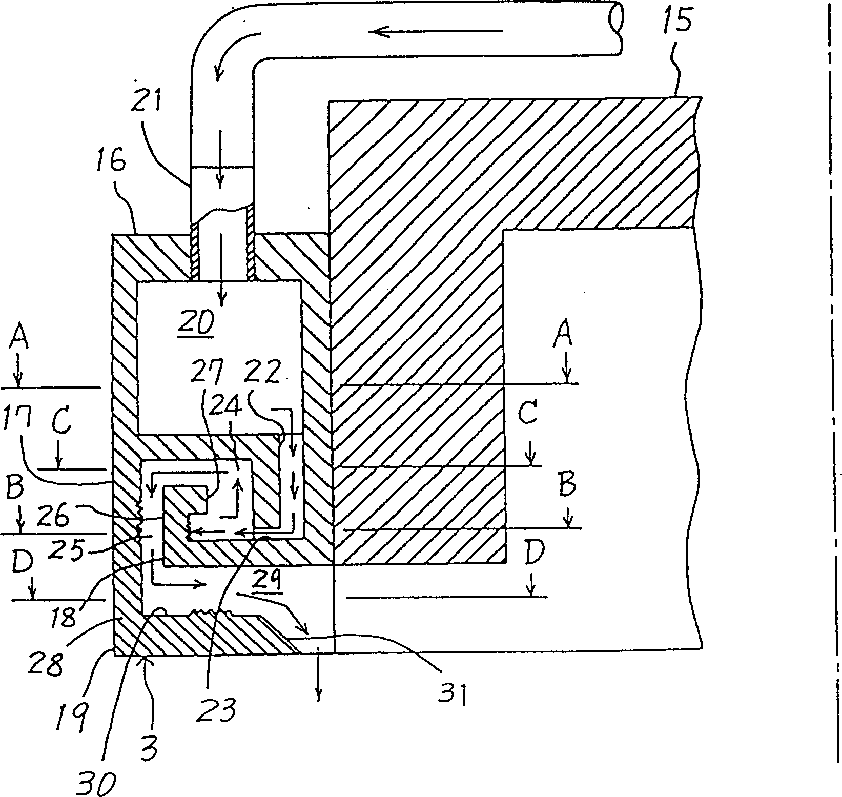
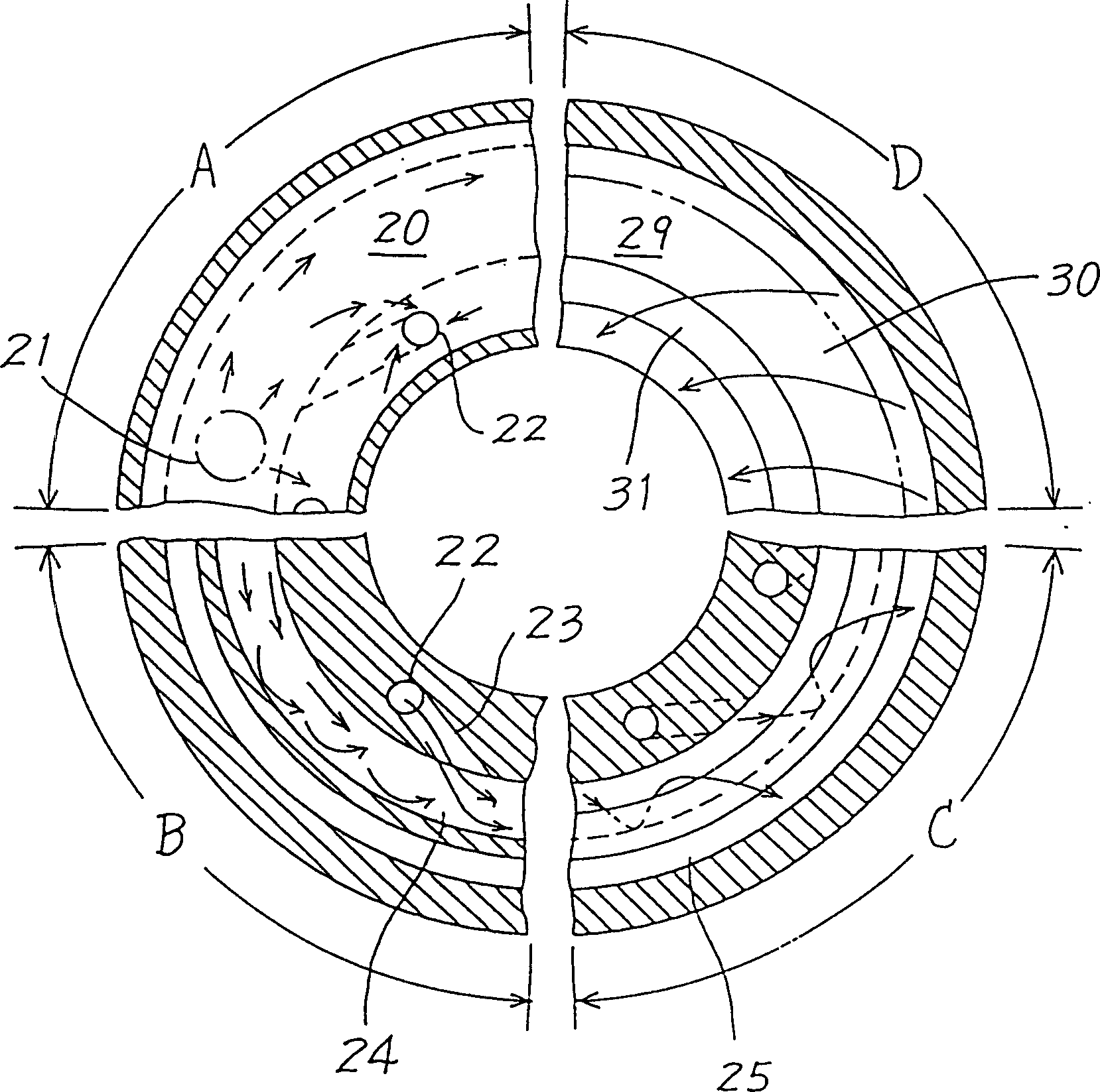
[0051] figure 1 The basic system structure of the present invention is shown in , the number 1 is a large-capacity main tank that can store coolant; 2 is a cooling pump (P1), in this example, it is used to suck air, generate air bubbles in the coolant and cool The liquid is sent into an annular nozzle 3. The annular nozzle 3 (described in detail below) is used to spray the cooling liquid sent in from the pump P1 downward in the form of a cylindrical cover 4 basically composed of a vortex formed by the confluence of granular turbulence, and impacts to on the surface of the workpiece 5. The workpiece 5 is cut on a movable platform 6 by a milling cutter 7 , which is a powerful cutting tool in this example, and a spindle 8 supporting the milling cutter passes through the annular nozzle 3 . Most of the cylinder 4 of coolant impinging on the workpiece surface at the lower end moves towards the center in a surface spiral flow to be sufficiently delivered to the contact between the ...


PUM


Abstract

A method and apparatus for feeding coolant liquid to a lathe with a nozzle (53) having a discharge port (58) of substantially rectangular cross section and a constricted curved surface portion (62) on its inner wall to produce a turbulent flow and a loosely mounted tongue piece (59) crossing the section of the discharge port and projecting outside the port. The coolant is thus discharged as a collection of particulate turbulent flows containing air bubbles drawn into the coolant liquid as it passes by the tongue piece. The coolant is caused to impinge on the rotating peripheral surface (56) which is continuous with the region of the workpiece in contact with the cutter (57).

Description

[0001] The patent application for the present invention was filed on February 12, 1997, with application number 97193816.4, and the title of the invention is a divisional application entitled "Supply of coolant in cutting machine tools and grinding machines and methods and devices for its separation and recovery". technical field [0002] The present invention relates to an apparatus for supplying cooling fluid in a cutting machine tool and a grinding machine, and for separating and recovering the same, and more particularly to a device for supplying a cooling fluid to the contact zone between cutting tools and the like and workpieces It also relates to a method and device for automatically separating and recovering cooling liquid after supply. Background technique [0003] In mechanical processing, the factors that play a major role in shortening the working hours and reducing the strain caused by processing are to enhance the contact lubrication between a cutting tool or gr...

Claims


Application Information

Patent Timeline
Patent Type & Authority Applications(China)
IPC IPC(8): B01D17/00B01D17/02B01D17/028B01D17/032B01D21/00B03D1/14B03D1/16B23Q11/00B23Q11/10
CPCY10S29/05B03D1/1418B01D17/0205B01D21/02B01D17/00B01D2221/14B23Q11/1069B03D1/1456B01D21/2488B01D21/283B03D1/1462B01D21/2455B03D1/028B01D21/003B23Q11/0053B03D1/14B03D1/1487B03D1/16Y10S82/901B01D21/0042Y10S29/077B01D21/009B03D1/247B23Q11/10B01D17/0208B01D17/0211B01D17/0214B01D17/045B23Q11/1061Y10T82/10Y10T407/14Y10T408/44Y10T408/46Y10T409/303752Y10T409/304032Y10T409/304088Y02P70/10B23Q11/00
Inventor 中井义和
Owner ZETA HEIWA
Why Eureka
Try Eureka