Method and system for encrypting bus using improved difference transition code

A differential and encoding technology, applied in encryption devices with shift registers/memory, transmission systems, digital transmission systems, etc., can solve data insecurity and other issues

Inactive Publication Date: 2004-04-28
IBM CORP
View PDF1 Cites 2 Cited by
  • Summary
  • Abstract
  • Description
  • Claims
  • Application Information

AI Technical Summary

Problems solved by technology

Therefore, the data is not secure becaus

Method used


Image

  • Method and system for encrypting bus using improved difference transition code
  • Method and system for encrypting bus using improved difference transition code
  • Method and system for encrypting bus using improved difference transition code

Examples


Embodiment Construction

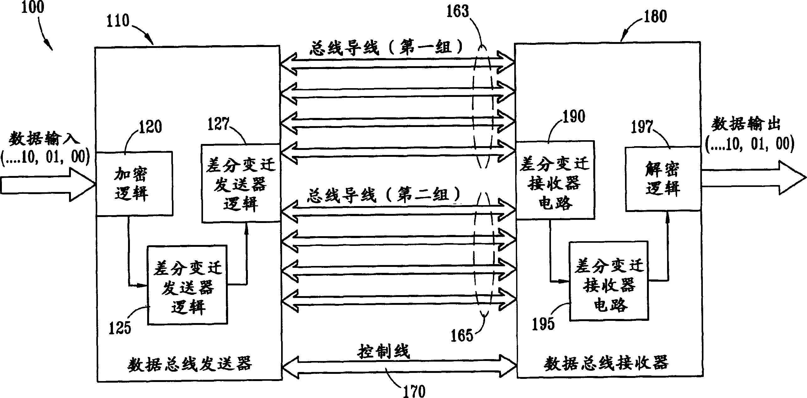
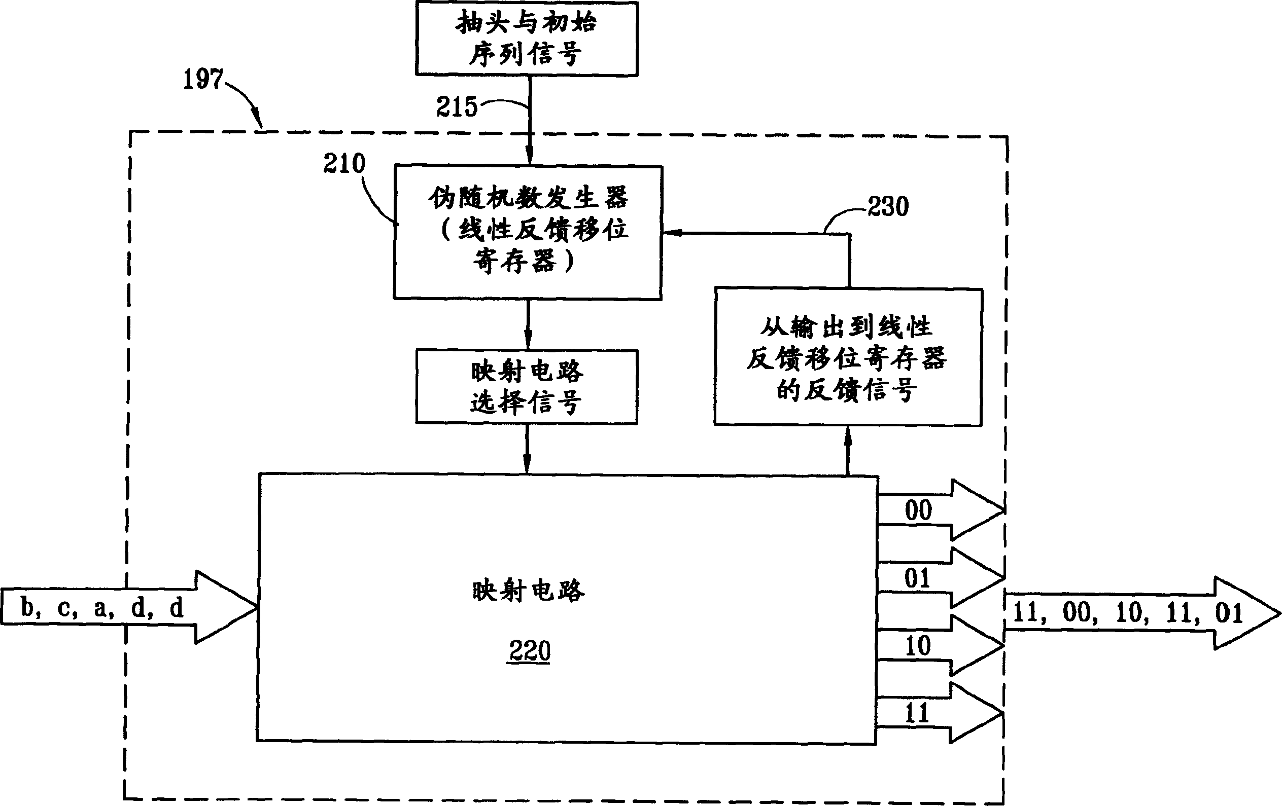
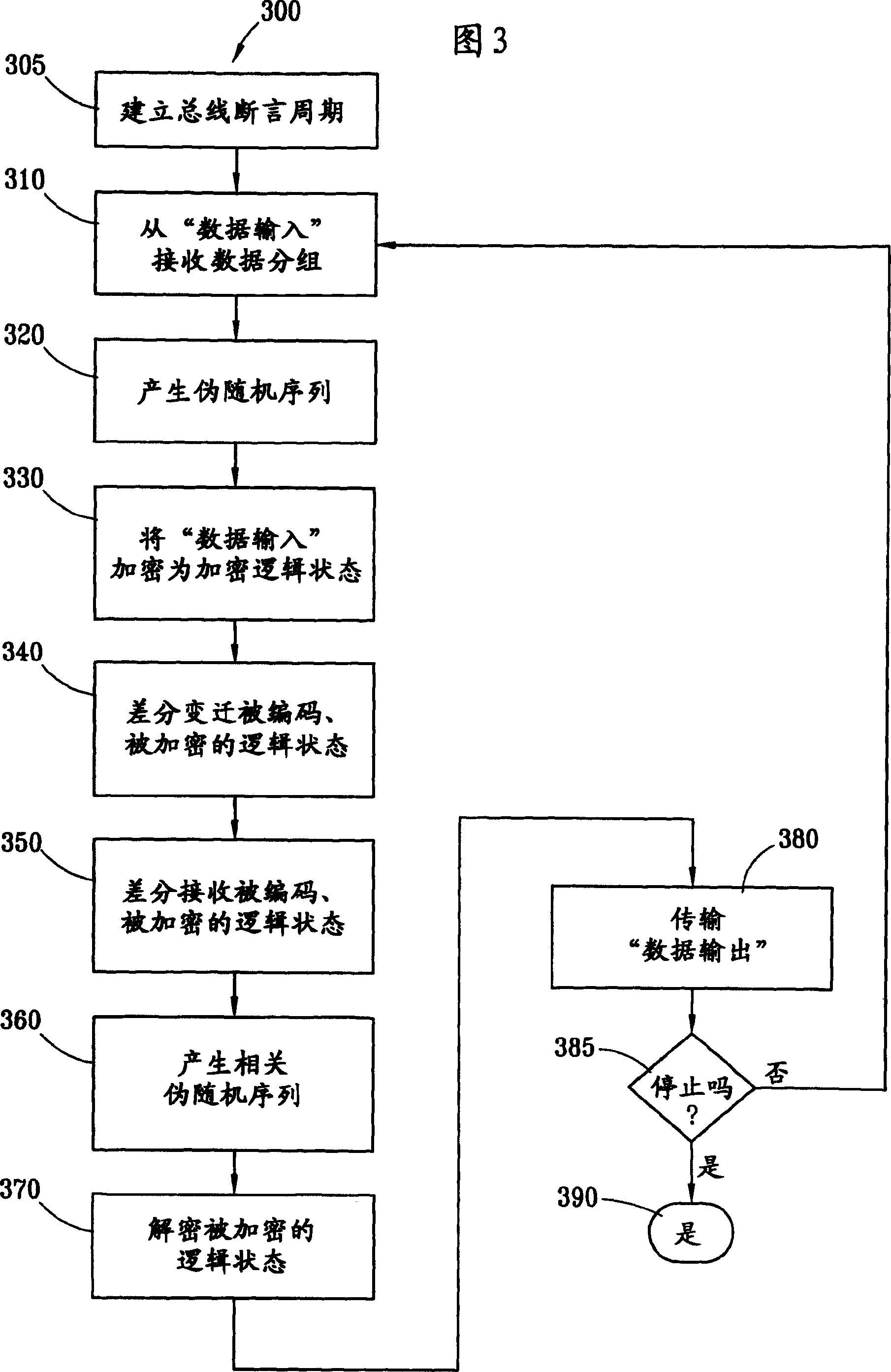
[0022] In the following discussion, numerous specific details are set forth in order to provide a thorough understanding of the present invention. However, it will be apparent to those skilled in the art that the present invention may be practiced without these specific details. In other instances, well-known components have been shown in schematic or block diagram form in order not to obscure the understanding of the present invention with unnecessary detail. In addition, descriptions of details regarding network communications, electromagnetic signaling techniques, etc. are generally omitted because these details are not necessary for a comprehensive understanding of the present invention and are believed to be within the knowledge of one of ordinary skill in the relevant art.

[0023] Note also that unless otherwise stated, all functions described herein may be implemented in hardware or software, or in a microprocessor executing firmware, or some combination thereof. In o...


PUM


Abstract

The present invention provides data encryption for a differential bus employing transitional coding. The present invention maps, encodes and encrypts input data as a logic status for a given bus transfer cycle. The mapping, encoding and encrypting of the input data changes from bus transfer cycle to bus transfer cycle. The mapping, encoding and encrypting is a function of a pseudo-random number. A logic status is differentially transmitted from a bus transmitter to a bus receiver, to be mapped, decrypted and decoded as the corresponding output data.

Description

technical field [0001] The present invention generally relates to a bus data transmission system, and more specifically, the present invention relates to a method and device for adopting data encryption for differential mode transitional coding (Transitional Coding). Background technique [0002] Today, the dramatic increase in circuit density and speed available in microchips has in turn required a corresponding increase in on-chip operating capabilities and performance. However, such improvements themselves start to create certain other problems, for example, the performance of conventional data bus technologies. It is increasingly difficult to provide very high off-chip input bandwidth and output bandwidth (i.e., data transfer to and from the microchip), because they need to effectively use this significantly increased On-chip operation capability. [0003] One solution to this dilemma is to use wider bus data paths. However, this approach requires an increased number ...

Claims


Application Information

Patent Timeline
IPC IPC(8): G06F13/38G09C1/00H03K3/84H04L9/18H04L9/20
CPCH04L9/065H04L2209/125H04L2209/34H04L9/0662
Inventor 戴维・J・克拉夫特查尔斯・R・约翰斯
Owner IBM CORP
Why Eureka
Try Eureka