
Production method for semiconductor chip

A manufacturing method, semiconductor technology, applied in semiconductor/solid-state device manufacturing, semiconductor devices, electrical components, etc., can solve problems such as difficult peeling

Inactive Publication Date: 2004-04-28
DISCO CORP
View PDF2 Cites 10 Cited by
  • Summary
  • Abstract
  • Description
  • Claims
  • Application Information

AI Technical Summary

Problems solved by technology

[0005] In addition, prefabricated cutting grooves are formed on the dividing roads on the surface of the semiconductor wafer. In the method of dividing individual semiconductor chips by grinding the back surface until the cutting grooves appear, it is called the so-called pre-dicing method. Paste the semiconductor wafer with cut grooves formed on the rigid plate support member before grinding, and extract the divided semiconductor chips from the plate support member after grinding without damaging the thin Semiconductor chip, it is also difficult to peel it off from the plate support member

Method used


Image

  • Production method for semiconductor chip
  • Production method for semiconductor chip
  • Production method for semiconductor chip

Examples


Embodiment Construction

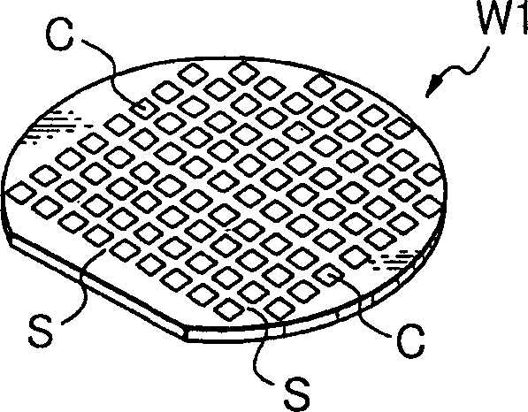
[0035] As the best mode for implementing the present invention, such as figure 1 As shown, a method of dividing a semiconductor wafer W1 having a plurality of semiconductor chips C formed on its surface by dividing by dividing streets S into individual semiconductor chips C will be described.

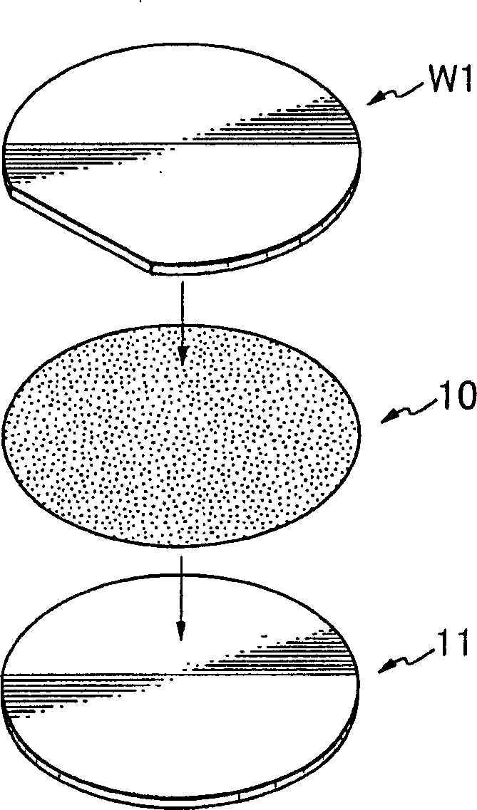
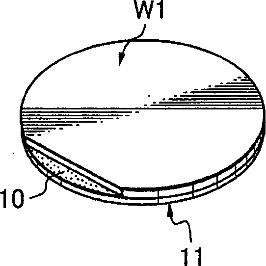
[0036] First, if figure 2 As shown, the semiconductor wafer W1 is turned over, and the surface of the semiconductor wafer W1 is pasted on the plate support member 11 through the adhesive tape 10, as shown in FIG. image 3 The state shown (plate support member integration process).

[0037] This adhesive tape 10 is an adhesive layer for adhering the semiconductor wafer W1 and the plate support member 11 , and is configured such that the adhesive force is reduced due to external factors. The sticking force mentioned here is composed of adhesive force and adhesion force. For example, adhesive tapes disclosed in JP-A-63-17981 and JP-A-4-88075 can be used as the adhesive tape 10 .

[00...


PUM


Abstract

A semiconductor wafer is applied to a support disk via an intervening adhesive layer with the front side of the semiconductor wafer facing the adhesive layer, which is sensitive to a certain exterior factor for reducing its adhesive force; the semiconductor wafer is ground on the rear side; the wafer-and-support combination is applied to a dicing adhesive tape with the so ground rear side facing the dicing adhesive tape, which is surrounded and supported by the circumference by a dicing frame; the certain exterior factor is effected on the intervening adhesive layer to reduce its adhesive force; and the intervening adhesive layer and support disk are removed from the semiconductor wafer or chips without the possibility of damaging the same.

Description

technical field [0001] The present invention relates to a method of manufacturing a semiconductor chip by grinding while supporting a semiconductor wafer using a plate support member. technical background [0002] On a semiconductor wafer, a plurality of circuits such as ICs and LSIs are formed, and are divided into individual semiconductor chips by dicing along the dividing lines on the surface, which are used in various electronic devices. [0003] The back surface of the semiconductor wafer is ground to form the required thickness. In recent years, since the miniaturization and weight reduction of electronic equipment has become possible, the semiconductor wafer is also required to be processed very thin, so that the thickness is less than 100 μm and less than 50 μm. However, the thinned semiconductor wafer is as soft as paper, and handling after grinding is difficult. Therefore, efforts have been made to perform polishing in a state where the semiconductor wafer is atta...

Claims


Application Information

Patent Timeline
Patent Type & Authority Applications(China)
IPC IPC(8): H01L21/00H01L21/301H01L21/304H01L21/44H01L21/68H01L21/78H01L21/784
CPCH01L21/3043H01L21/78H01L21/67132Y10S438/977
Inventor 北村政彦矢岛兴一木村祐辅田渕智隆
Owner DISCO CORP
Learn More