
Lightning protection antiinterference capactive transformer
A technology for transformers and three-phase transformers, applied in the field of transformers, can solve problems such as adverse effects of switchgear and protection device setting, reduce transformer impedance voltage drop, adverse lightning strike and interference prevention, etc., so as to eliminate additional losses, reduce quantity and The effect of investment and improved sensitivity
- Summary
- Abstract
- Description
- Claims
- Application Information
AI Technical Summary
Problems solved by technology
Method used
Image

Examples
Embodiment Construction
[0045] Below in conjunction with accompanying drawing and embodiment the present invention is described in further detail:
[0046] First, the low-voltage winding of the transformer is described.
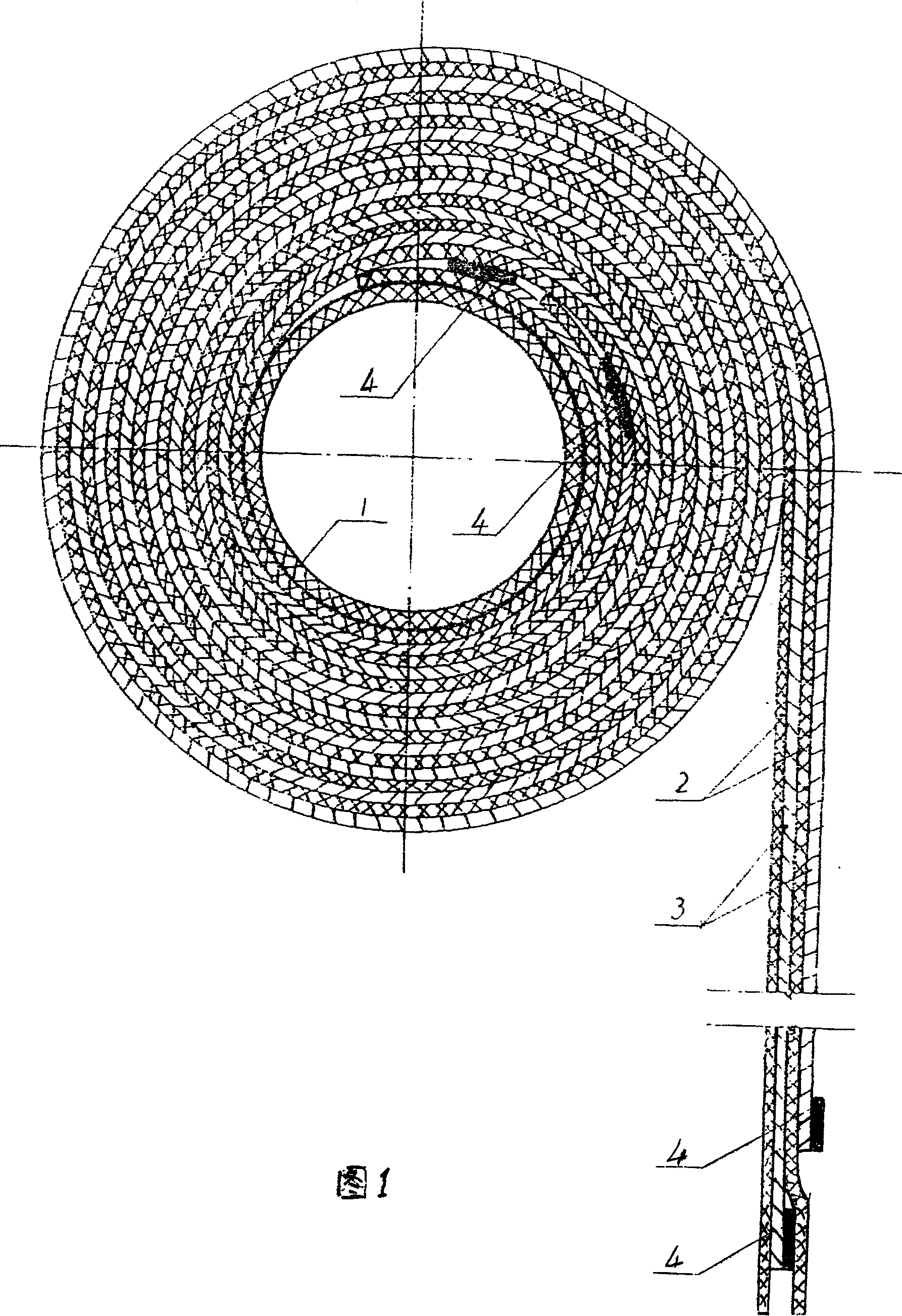
[0047] Shown in Fig. 1 is the structure of the winding of the present invention. In the present invention, one layer of insulating layer 3, one layer of metal foil 2, another layer of insulating layer 3, and another layer of metal foil 2 are separated from each other and stacked, and wound on the inner insulating cylinder 1 (the inner insulating cylinder 1 is also may be formed by the first insulating layer 3 itself). After the winding is completed, an outer insulating layer 3 is wrapped on the surface of the outer metal foil 2 of the winding. (The metal foil 2 can also be placed in the innermost layer, and the insulating layer 3 of the outer layer after winding naturally forms the outer insulating layer of the winding, and then is properly coated with a reinforced insulating mate...
PUM
 Abstract
Description
Claims
Application Information