Optical pickup device
A technology of optical pickup device and bobbin, which is applied in optical recording head, head configuration/installation, optical recording/reproduction, etc., and can solve problems such as deterioration of objective lens characteristics, uneven temperature distribution, etc.
- Summary
- Abstract
- Description
- Claims
- Application Information
AI Technical Summary
Problems solved by technology
Method used
Image
Examples
no. 1 example
[0023] Hereinafter, a pickup device 1 according to a first embodiment of the present invention will be described with reference to the drawings.
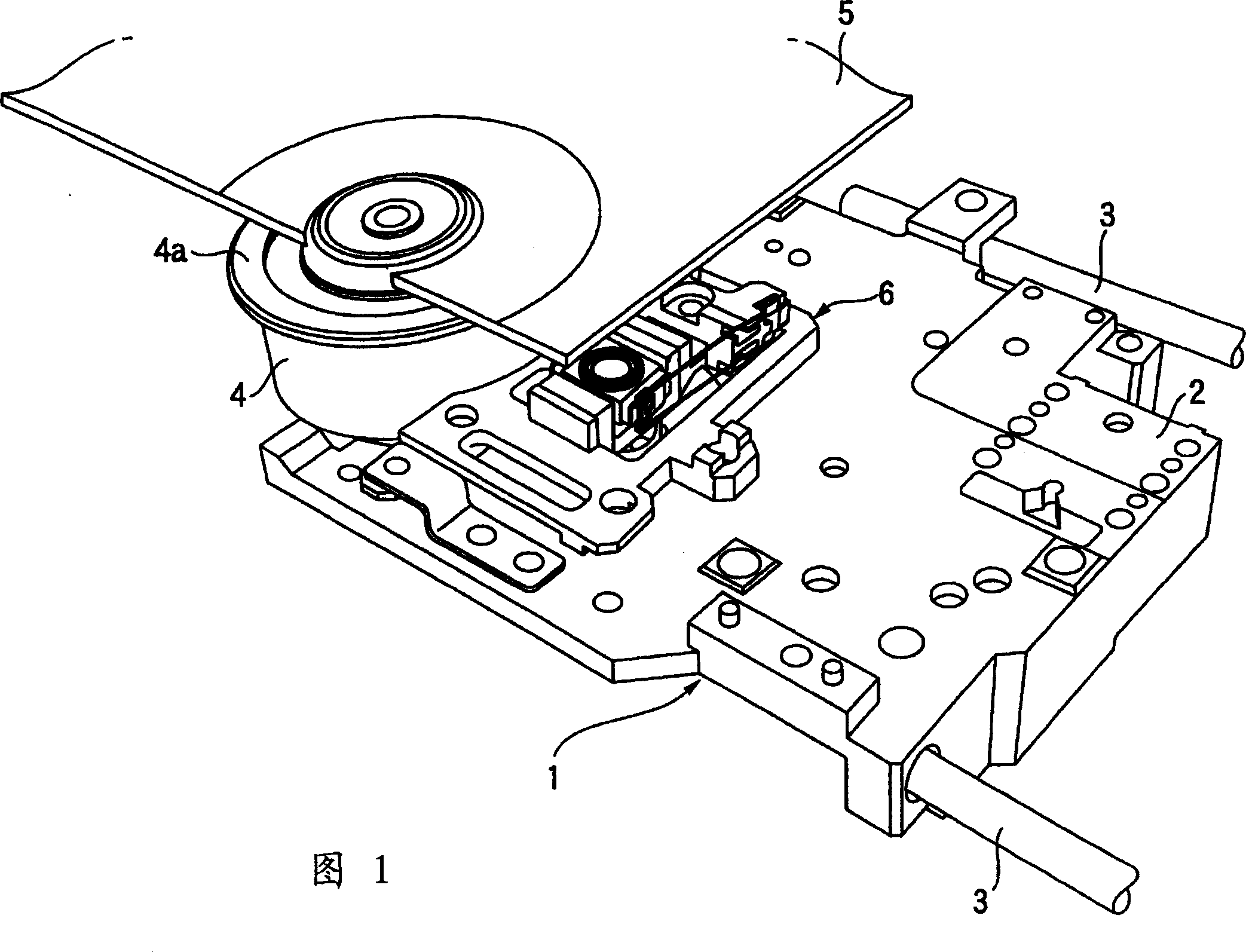
[0024] Fig. 1 is a perspective view of a pickup device 1 according to a first embodiment of the present invention. The pickup device 1 is provided in an optical disc unit such as a CD player and a DVD player. The pick-up device 1 includes a pick-up device body 2 movably placed on guide shafts 3 and 3 , and an actuator 6 fixedly placed on the pick-up device body 2 . The pickup device 1 is opposed to the recording side of the optical disc 5 placed on the disc placement part 4 a which is rotatable via the rotary shaft 4 .
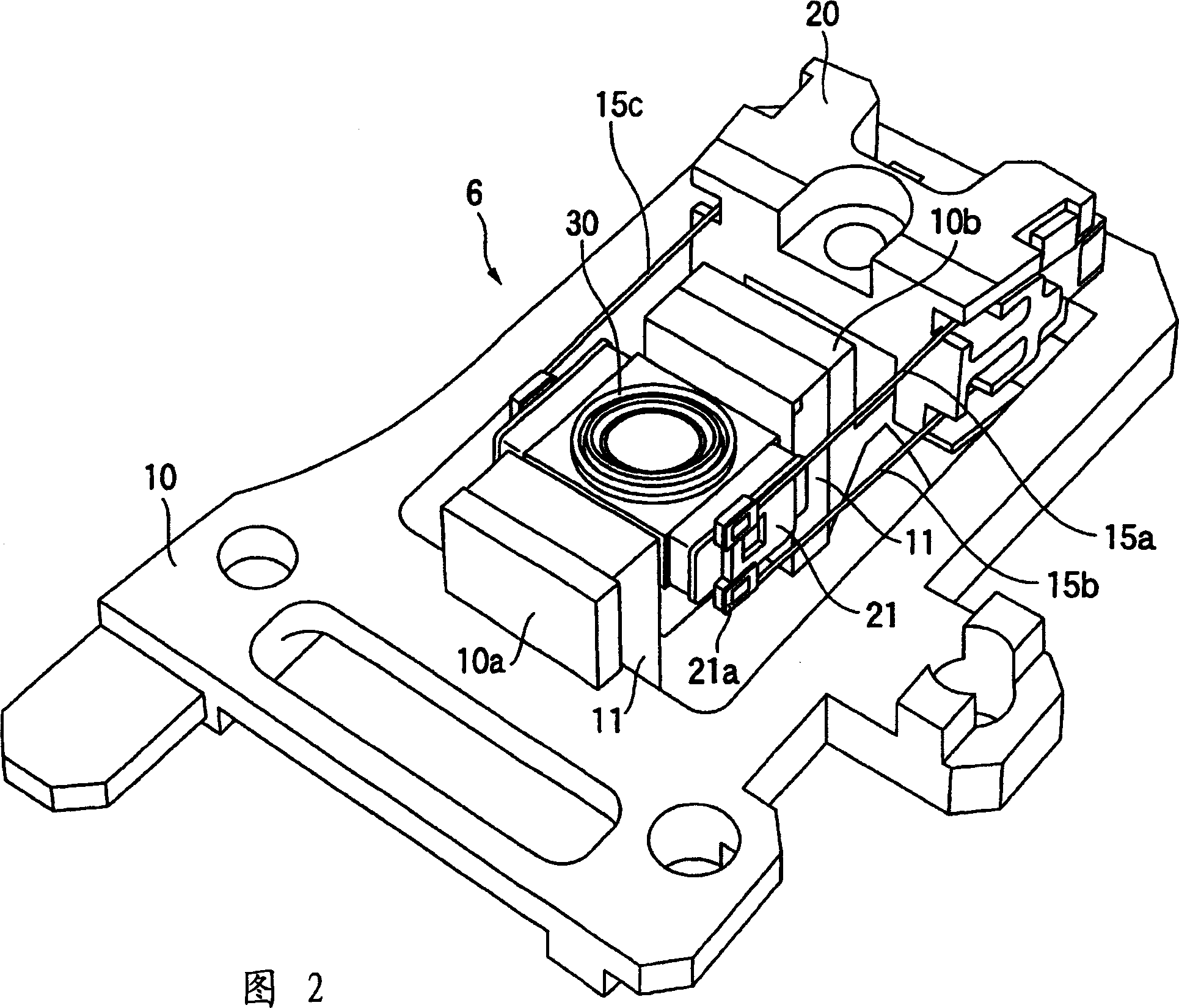
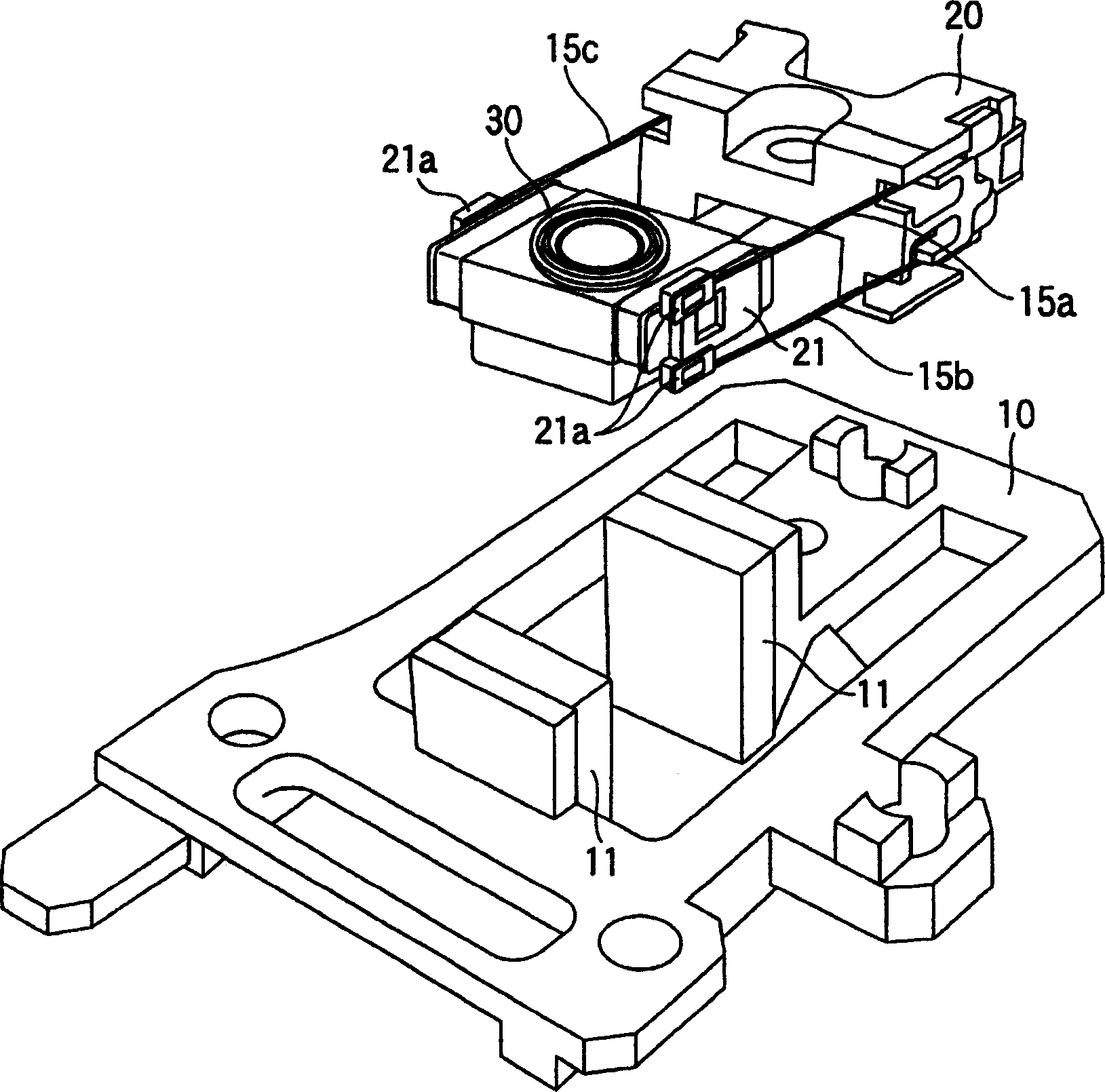
[0025] Fig. 2 is an enlarged perspective view of the actuator 6 of the pick-up device. image 3 is an exploded perspective view of the actuator 6 . The actuator 6 has a yoke 10 , an actuator fixing portion 20 , and an actuator moving portion 30 that can move very slightly relative to the yoke 10 and the actuator f...
no. 2 example
[0040] Hereinafter, a pickup device according to a second embodiment of the present invention will be described with reference to the accompanying drawings.
[0041] Image 6 is a perspective view of the actuator moving part 40 of the present embodiment, Figure 7 is a cross-sectional view of the moving part 40 of the actuator. The actuator moving section 40 includes an objective lens 41 , a bobbin 42 , an insertion member 43 , a pair of tracking coils 44 , and a focusing coil 45 .
[0042] The bobbin 42 is a resin member having a tracking coil holding portion 42a for winding the tracking coil around it on the opposite side, and includes a through hole 42b as a lens storage hole shaped like a cylinder, Penetrates up and down along the axis. The bobbin 42 is formed with an aperture portion 42f extending radially inward from the peripheral surface of the through hole 42b. The aperture portion 42f matches the diameter of the laser light incident on the objective lens 41 to th...
no. 3 example
[0050] Hereinafter, a pickup device according to a third embodiment of the present invention will be discussed with reference to the accompanying drawings.
[0051] Figure 8 is a perspective view of the actuator moving part 50 in this embodiment, Figure 9 is a cross-sectional view of the moving part 50 of the actuator. The actuator moving section 50 includes an objective lens 51 , a bobbin 52 , an insertion member 53 , a pair of tracking coils 54 , and a focusing coil 55 .
[0052] The difference between the actuator moving part 50 of the present embodiment and the actuator moving part 40 in the second embodiment is that the insertion element 53 has been improved on the insertion element 43; The components 41, 42, 44 and 45 are the same in the two embodiments.
[0053] The insertion element 53 in the third embodiment is a circular plate-like element in plan view. It has almost the same shape as one side of the stepped portion 52e of the bobbin 52, and is fixed in close c...
PUM
 Abstract
Description
Claims
Application Information
 - R&D
- Intellectual Property
- Life Sciences
- Materials
- Tech Scout
- Unparalleled Data Quality
- Higher Quality Content
- 60% Fewer Hallucinations
Browse by: Latest US Patents, China's latest patents, Technical Efficacy Thesaurus, Application Domain, Technology Topic, Popular Technical Reports.
© 2025 PatSnap. All rights reserved.Legal|Privacy policy|Modern Slavery Act Transparency Statement|Sitemap|About US| Contact US: help@patsnap.com


