High property passive cooling device with conduit

A passive cooling, core column technology, applied in the direction of semiconductor devices, semiconductor/solid-state device components, electrical components, etc., can solve problems such as adding fans and heat sinks, device or PC board failure, and inability to install in vertical spaces. , to increase the surface area

Inactive Publication Date: 2004-05-12
HEWLETT PACKARD DEV CO LP
View PDF0 Cites 7 Cited by
  • Summary
  • Abstract
  • Description
  • Claims
  • Application Information

AI Technical Summary

Problems solved by technology

[0006] Increasing the size of the fan and heatsink has some disadvantages
First, if the size of the heatsink increases vertically (i.e., in the direction perpendicular to the PC board), the heatsink is taller, making it impossible to fit in the vertical space in many applications, such as in the case of a desktop computer
Second, if the PC board has a vertical orientation, a tall and heavy heatsink may mechanically stress the PC board and/or electronics, resulting in failure of the device or PC board
Fifth, when a heat sink has a cylindrical shape composed of cooling fins, usually ...

Method used


Image

  • High property passive cooling device with conduit
  • High property passive cooling device with conduit
  • High property passive cooling device with conduit

Examples


Embodiment Construction

[0047] In the following detailed description and drawings, the same elements are denoted by the same reference numerals.

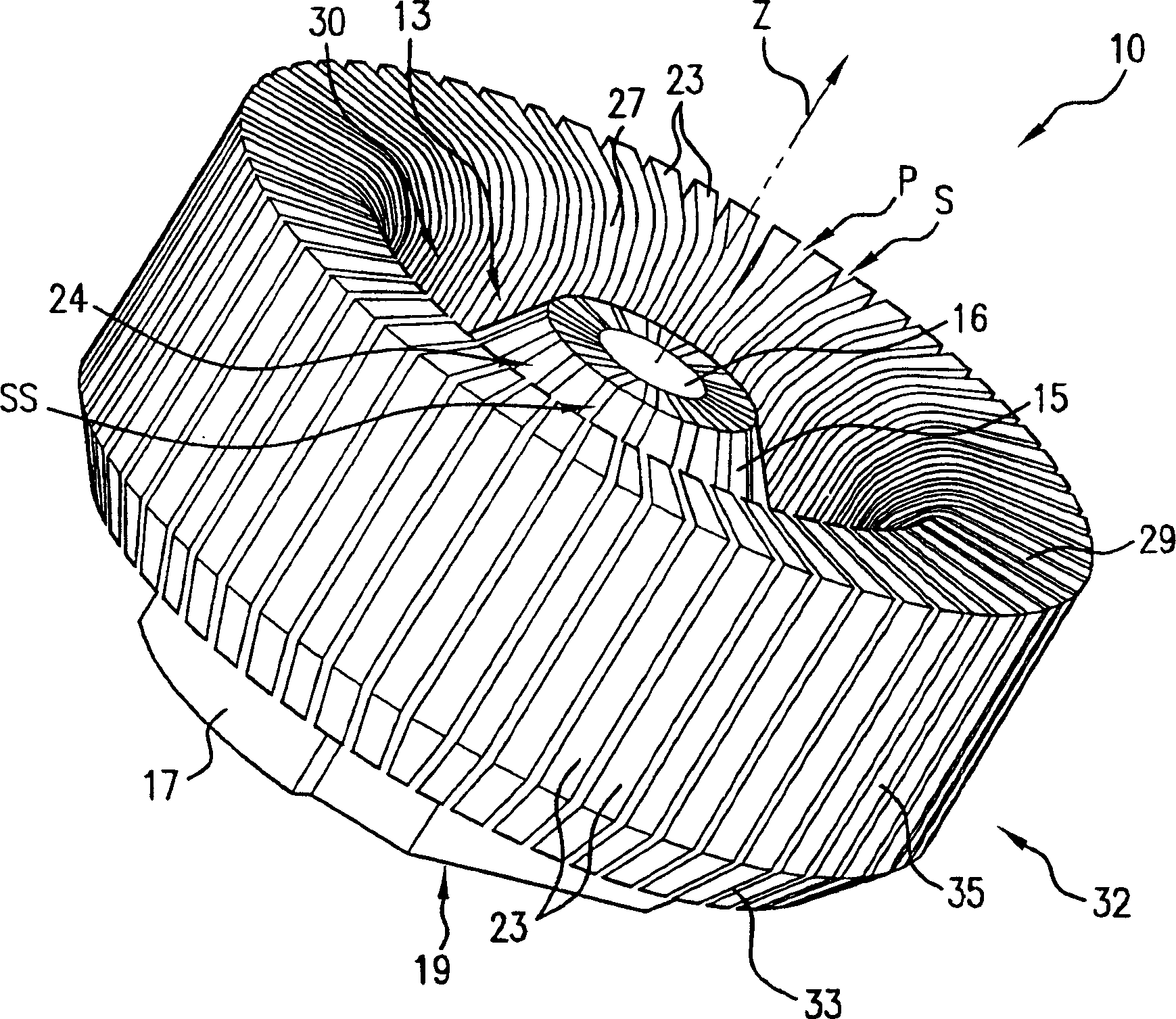
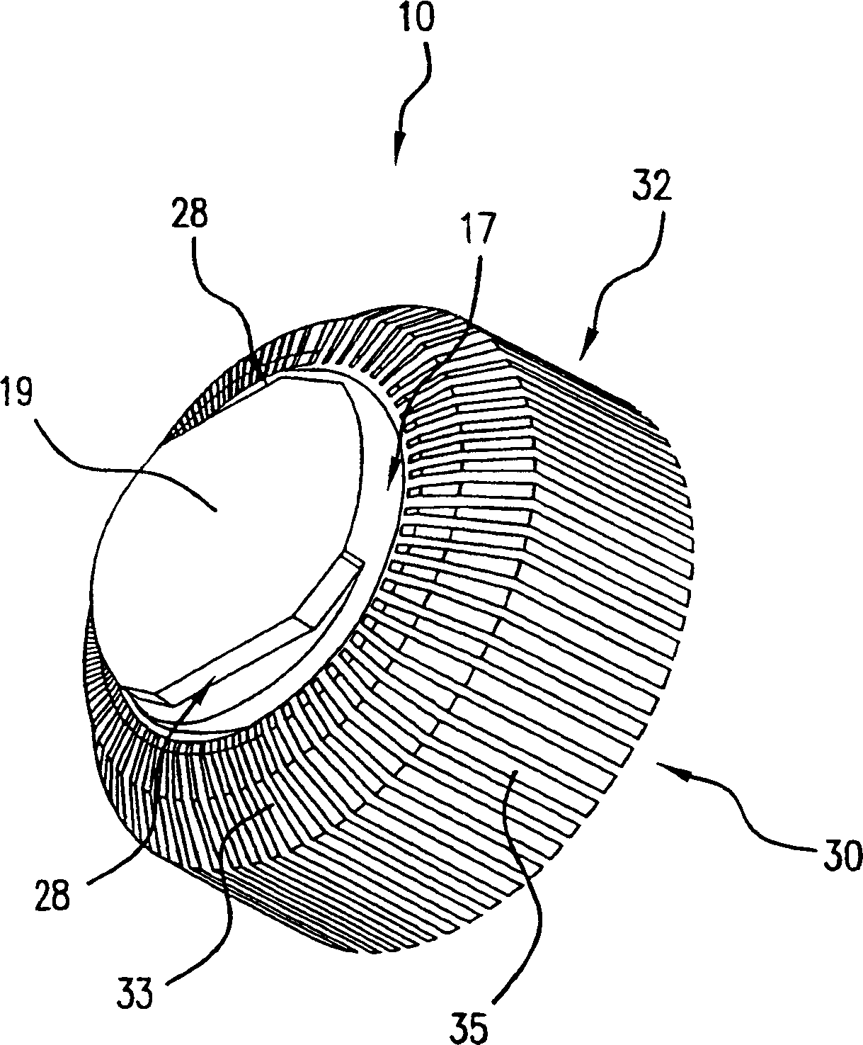
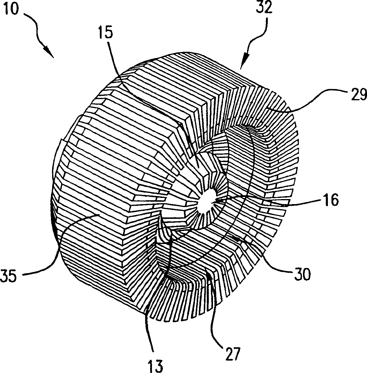
[0048] As shown in the drawings used to illustrate the invention, the invention is embodied in a passive cooling device for dissipating heat from the element to be cooled. The passive cooling device includes a thermal body, and a stem connected to the thermal body and extending to the outside of the thermal body. The stem is disposed symmetrically about the axis of the thermal body, the stem includes a diverter surface, an end face and a plurality of stem fins spaced apart to define between adjacent stem fins A stem slot. The stem groove extends toward the heating body. A thermally conductive base is in contact with the thermal body and includes a mounting surface suitable for thermally coupling the thermal body to the component.

[0049] A plurality of vanes, which are connected to the thermal body, are spaced apart to define primary slots between adja...


PUM


Abstract

A passive cooling device 10 for removing waste heat from a component 50 is disclosed. The passive cooling device 10 includes a heat mass 11 and a stem 13 extending outward therefrom and including a plurality of fins 24 with stem slots SS therebetween. A plurality of vanes 21 that include fins 23 formed therein surround the stem 13 and define a chamber 30. A duct 90 connects with a top face 29 of the vanes 21 and an air flow source 70 that generates an air flow F through the chamber 30, the stem fins 24, the fins 23, and the vanes 21 to dissipate heat from the heat mass 11. The air flow source 70 can supply a positive FP or a negative FN air flow.

Description

technical field [0001] The present invention generally relates to a passive cooling device for dissipating heat from components to which it is connected. More specifically, the present invention relates to a passive cooling device for dissipating heat from components connected thereto, and including conduits for directing an air flow between a source of air flow and the passive cooling device. Background technique [0002] In the field of electronic devices, it is known to bring a heat sink and the electronic device into contact so that waste heat generated by the operation of the electronic device is thermally transferred to the heat sink, thereby cooling the electronic device. With the advent of high clock speed electronic devices such as microprocessors (μP), digital signal processors (DPS) and application specific integrated circuits (ASICs), the amount of waste heat generated by these electronic devices and the operating temperature of these electronic devices Proporti...

Claims


Application Information

Patent Timeline
IPC IPC(8): H01L23/36H01L23/467
CPCH01L2924/0002H01L23/467H01L2924/00
Inventor S·赫奇
Owner HEWLETT PACKARD DEV CO LP
Why Eureka
Try Eureka