Heat treatment apparatus

A technology for heat treatment devices and furnaces, which is applied to furnace control devices, maintenance of heating chambers, lighting and heating equipment, etc. It can solve the problems of not adjusting the zero point and difficult to maintain measurement accuracy

Inactive Publication Date: 2004-05-12
TOKYO ELECTRON LTD
View PDF1 Cites 4 Cited by
  • Summary
  • Abstract
  • Description
  • Claims
  • Application Information

AI Technical Summary

Problems solved by technology

Therefore, film thickness deviation, which was not a problem before, becomes a problem
[0006] In addition, the differential pressure gauge is used to measure small differential pressure and does not adjust the zero point.
Therefore, in the case of long-term use, it is difficult to maintain measurement accuracy

Method used


Image

  • Heat treatment apparatus
  • Heat treatment apparatus
  • Heat treatment apparatus

Examples


Embodiment Construction

[0023] Hereinafter, embodiments of the present invention will be described in detail with reference to the drawings.

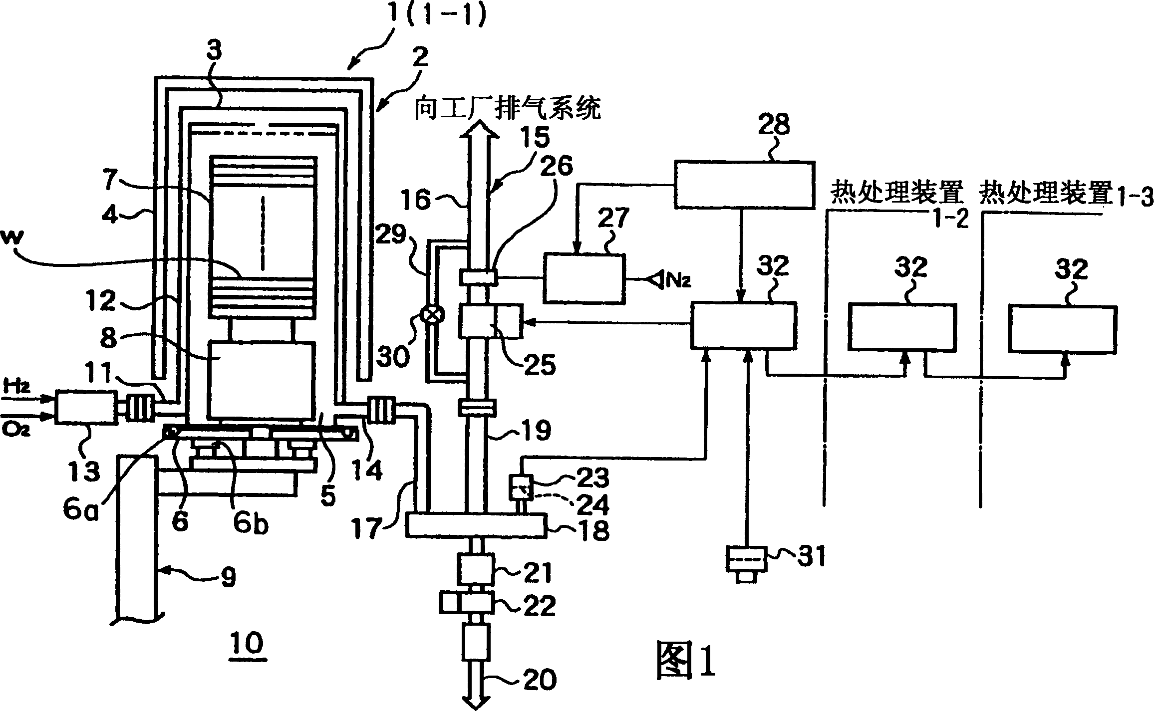
[0024] In FIG. 1, reference numeral 1 denotes a heat treatment apparatus configured for thermal oxidation treatment. The heat treatment apparatus 1 has a vertical batch type treatment furnace 2 . After the semiconductor wafer W is placed in the processing furnace 2, a processing gas is introduced into the processing furnace 2, and a thermal oxidation treatment is performed at a high temperature of about 850°C. As the processing gas when performing the thermal oxidation treatment, a gas containing moisture (for example, a mixed gas of water vapor or water vapor and hydrogen chloride gas) and a gas capable of reacting in the treatment furnace 2 to generate moisture (for example, hydrogen chloride gas and hydrogen chloride gas) can be used. Oxygen mixture). The processing furnace 2 has a vertically long cylindrical shape with a closed upper end and an open lowe...


PUM


Abstract

Exhaust pressure in an exhaust system 15 that evacuates a processing furnace 2 is determined as absolute pressure by using a differential manometer 23, which measures the exhaust pressure as differential pressure, and a barometer (31), which measures atmospheric pressure as absolute pressure. An opening of a pressure regulating valve 25 is adjusted based on the absolute exhaust pressure thus determined so that pressure in the processing furnace 2 is regulated.

Description

technical field [0001] The invention relates to a heat treatment device, in particular to a pressure control technology in a treatment furnace. Background technique [0002] In the manufacturing process of semiconductor devices, there is an oxidation treatment process for forming an oxide film on the surface of a semiconductor wafer as one of heat treatments. As one method of oxidation treatment, there is a method of oxidizing a semiconductor wafer by contacting it with water vapor at a predetermined treatment temperature in a treatment furnace (wet oxidation). An apparatus for wet oxidation treatment is described in Japanese Patent Application Laid-Open No. 63-210501. This device has a combustion device outside the treatment furnace that reacts hydrogen and oxygen to generate water vapor, and supplies the water vapor generated by the combustion device into the treatment furnace for heat treatment. [0003] In this heat treatment device, there is an exhaust system that is ...

Claims


Application Information

Patent Timeline
Patent Type & Authority Applications(China)
IPC IPC(8): C23C16/455C23C16/44C23C16/52F27B5/16F27B5/18F27D7/06F27D19/00H01L21/00H01L21/22H01L21/31
CPCC23C16/52C23C16/4412H01L21/67109H01L21/324
Inventor 斋藤幸正
Owner TOKYO ELECTRON LTD
Why Eureka
Try Eureka