Magnetic inductor and its manufacturing method
A magnetic sensor, magnetization direction technology, applied in field-controlled resistors, electromagnetic device manufacturing/processing, etc., can solve problems such as insufficiency, offset stability, etc.
- Summary
- Abstract
- Description
- Claims
- Application Information
AI Technical Summary
Problems solved by technology
Method used
Image

Examples
no. 1 example
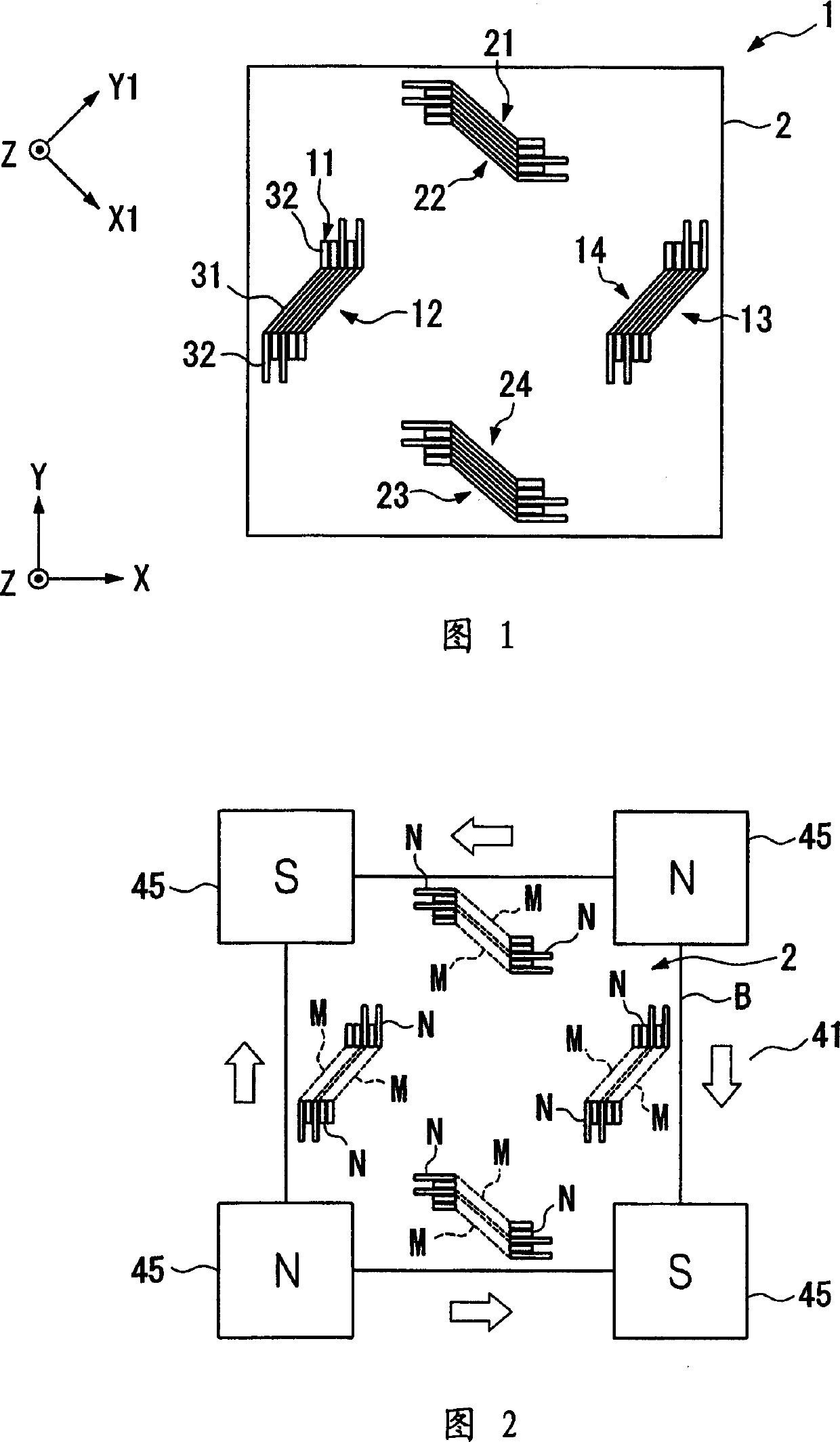
[0107] 1 is a plan view of a biaxial magnetic sensor using a GMR element according to a first embodiment of the present invention.
[0108] That is, the magnetic sensor 1 includes a quartz substrate 2 having a prescribed thickness and an approximately square shape, and X-axis GMR elements 11 to 14 are disposed on the quartz substrate 2 to form an X-axis magnetic sensor for detecting a magnetic field in an X1-axis direction, The Y-axis GMR elements 21 to 24 are disposed on the quartz substrate 2 to form a Y-axis magnetic sensor for detecting a Y1-axis direction magnetic field perpendicular to the X1-axis direction. Specifically, the induction direction of the X-axis magnetic sensor is the X1-axis direction at an angle of 45 degrees to the X-axis direction, and the magnetic induction direction of the Y-axis magnetic sensor is the Y1-axis direction at a 45-degree angle to the Y-axis direction.
[0109] Above, silicon can be used instead of the material of the quartz substrate 2 ....
no. 3 example
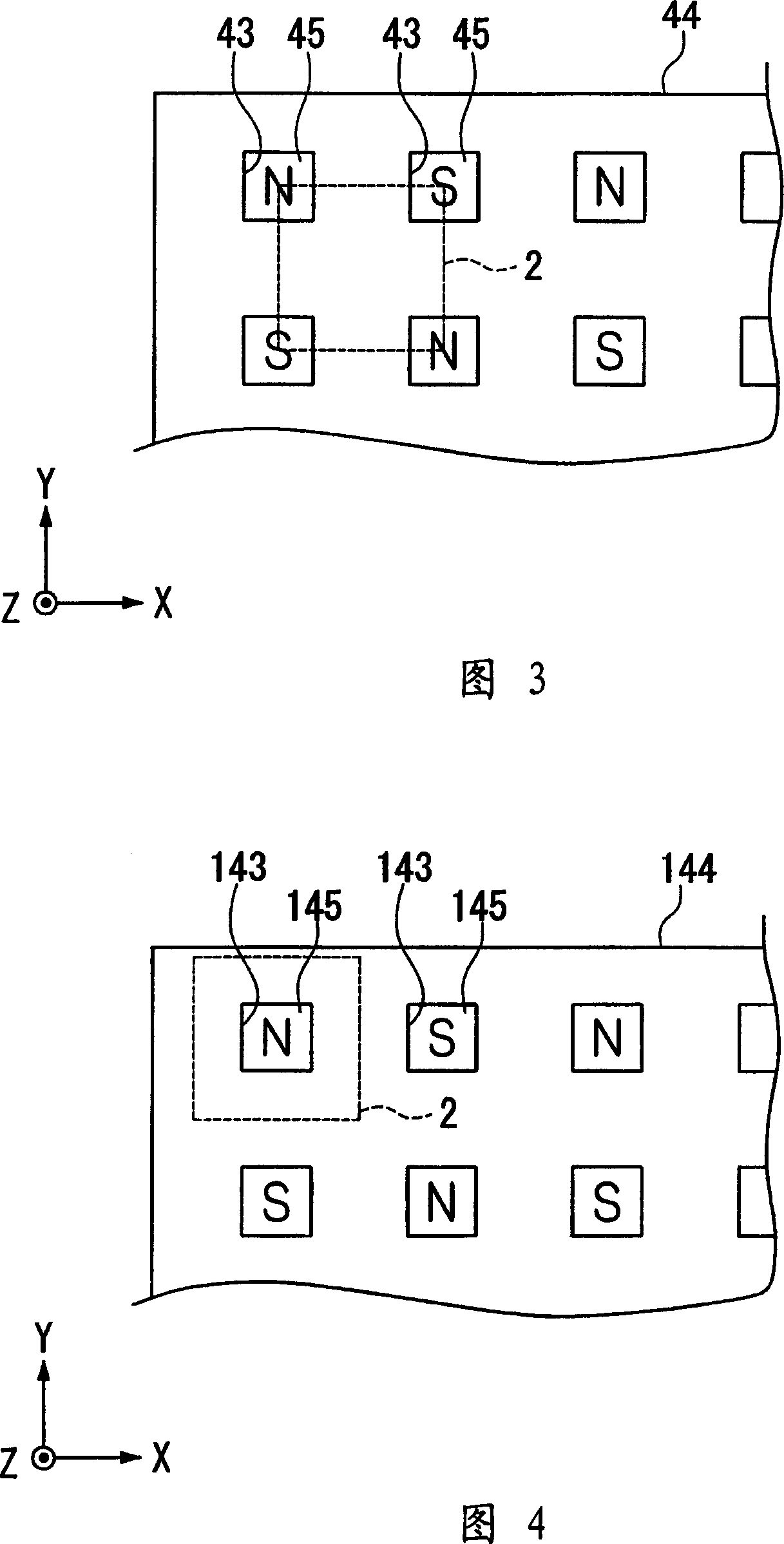
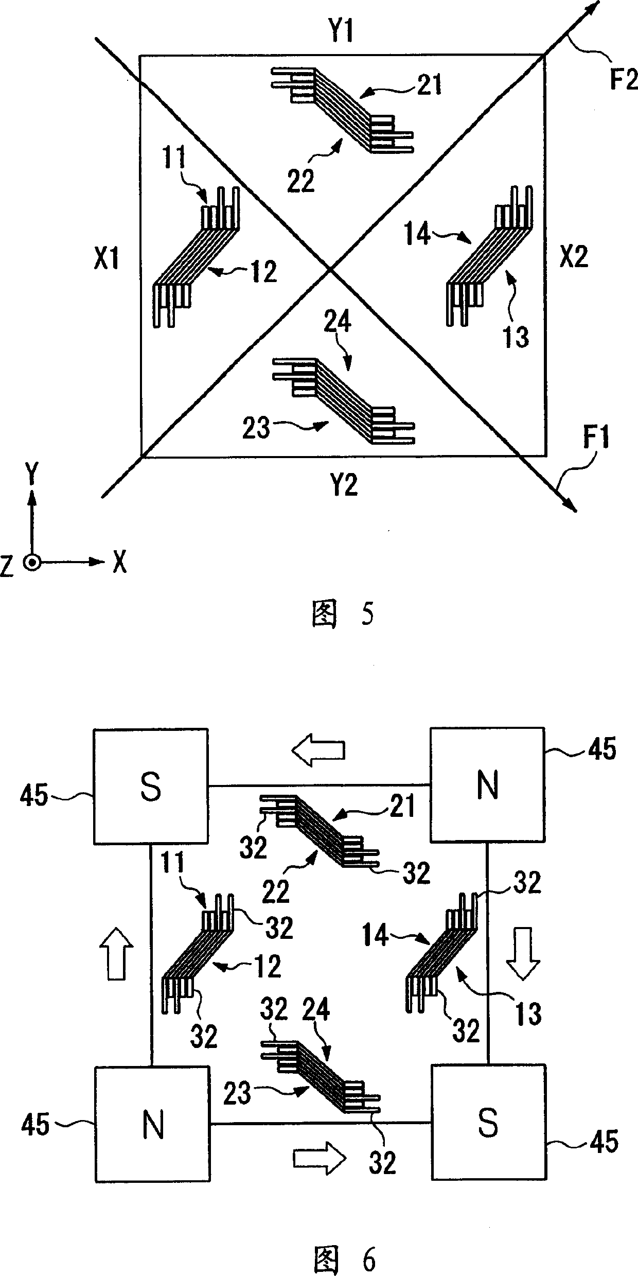
[0186] The second embodiment uses a magnet array having the same structure as the magnet array used in the first embodiment in order to sufficiently attach the permanent magnet 45 and the magnetized permanent magnet film 32 . Here, the magnetization of the permanent magnet film 32 can be realized by directly using the magnet array for the sequential heat treatment in the aforementioned second embodiment without changing the arrangement position of the magnets.
[0187] In the magnetization, a magnetic field at an angle of 45 degrees to one side of the quartz substrate 2 is established along the diagonal of the quartz substrate 2 separated in the subsequent division process. Accordingly, a magnetic field acts on the permanent magnet film 32 in a direction at an angle of 45 degrees to the longitudinal direction of the permanent magnet 32 parallel to one side of the quartz substrate 2 .
[0188] In this way, the terminal of the free layer F is initialized to be the same as the ...
no. 4 example
[0192] 23 shows a plan view of a magnetic sensor according to a fourth embodiment of the present invention, wherein, similar to the previous embodiments, the magnetic sensor 81 of the fourth embodiment is composed of a GMR element and a permanent magnet film provided on a quartz substrate 2. Here, the magnetic sensor 81 is different from the magnetic sensor 50 in the second embodiment. The X-axis GMR elements 51-52 of the former are arranged parallel to each other near the midpoint of one side of the quartz substrate 2 in the negative direction of the X-axis, Y The axis GMR elements 63-64 are arranged parallel to each other near the midpoint position of the other side of the quartz substrate 2 in the negative direction of the Y axis, thereby eliminating the interference caused by the X axis GMR elements 51-52 and the Y axis GMR elements 63-64. Sensitivity, they are arranged substantially in the center of the quartz substrate 2 and at an angle of 45 degrees to a prescribed side ...
PUM
 Abstract
Description
Claims
Application Information
 - R&D
- Intellectual Property
- Life Sciences
- Materials
- Tech Scout
- Unparalleled Data Quality
- Higher Quality Content
- 60% Fewer Hallucinations
Browse by: Latest US Patents, China's latest patents, Technical Efficacy Thesaurus, Application Domain, Technology Topic, Popular Technical Reports.
© 2025 PatSnap. All rights reserved.Legal|Privacy policy|Modern Slavery Act Transparency Statement|Sitemap|About US| Contact US: help@patsnap.com