

Anisotropically bonded magnet and fabricating method, magnetic path thereof
A bonded magnet, anisotropic technology, applied in the manufacture of inductors/transformers/magnets, circuits, electrical components, etc., can solve the problems of decreased mechanical strength, unmaintainable shape, decreased magnetic properties, etc., to improve mechanical strength and protection. Magnetic properties, effect of improving lubricity
Inactive Publication Date: 2010-08-25
SEIKO INSTR INC
View PDF9 Cites 15 Cited by
- Summary
- Abstract
- Description
- Claims
- Application Information
AI Technical Summary
Problems solved by technology
However, for example, if the amount of magnetic powder is increased in order to improve magnetic properties, there is a problem that the amount of thermosetting resin (binder) binding the magnetic powder will decrease, and the mechanical strength will decrease.
However, the agglomeration, segregation, separation and cross-linking of micropowder are relatively severe. Even if the orientation magnetic field becomes stronger, it is difficult to move the micropowder to the desired direction and position, and the degree of orientation has always been low.
That is, since the degree of orientation is always low even if the density is increased, the magnetic properties are not ideal
In addition, due to the agglomeration, segregation, separation and cross-linking of the micropowder, the magnetic powder is unevenly filled in the forming metal mold. Decreased performance and corrosion resistance
According to this, there is a problem that the magnetic properties will further decrease, and the mechanical strength, heat resistance, and corrosion resistance will decrease due to the density (inhomogeneity) of the filling.
Due to the formation of the cavities (voids) 107, there is a problem that the magnetic powder is densified, the magnetic properties are degraded, and the mechanical strength of the anisotropic bonded magnet is degraded.
There is also a problem that the shape of the compressed powder body cannot be maintained even when it is taken out from the forming metal mold.
Method used
View moreImage
Smart ImageViewing Examples

Examples
Embodiment 1
Embodiment 2
Embodiment 8
Login to View More PUM
| Property | Measurement | Unit |
|---|---|---|
| particle size | aaaaa | aaaaa |
| particle size | aaaaa | aaaaa |
| particle size | aaaaa | aaaaa |
Abstract
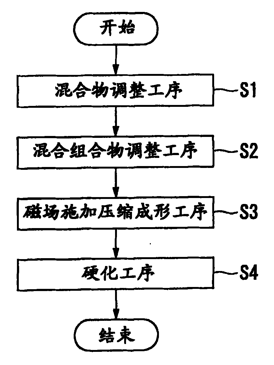
This invention relates to a fabricating method for anisotropically bonded magnet including: step S1 for adjusting the first mixture and the second mixture, where: the first mixture comprises the first magnetic powder, of which the grain size is in the range of 20-150mum, thermosetting resin of 2.0 wt%being added into the anisotropically bonded magnet, the first additive; the second mixture comprises the second magnetic powder, of which the grain size is in the range of 1-20mum, the second additive; step S2 for adjusting the first mixture and the second mixture; step S3 for making the magnetic intensity of the end part of the shaping metal die be under the 0.8T, the magnetic intensity of the central part of the shaping metal die is 5% higher than that of the said end part of the shaping metal die after said mixed compounds being filled into the metal die; step S4 for heating said mixed compounds at the atmosphere of inert gases or nitrogen gases so as to harden compounds.
Description
technical field The invention relates to a manufacturing method of an anisotropic bonded magnet, a magnetic circuit and an anisotropic bonded magnet. Background technique Permanent magnets are divided into bonded magnets (Bonded magnets), sintered magnets, cast magnets and the like. A bonded magnet refers to a composite permanent magnet formed by solidifying magnet powder with a binder. Main components are magnet powder and binder, and lubricant etc. are added as needed. Compared with sintered magnets, bonded magnets have poorer magnetic properties than sintered magnets due to the inclusion of a binder, but compared with sintered magnets, they have higher dimensional accuracy, higher degree of shape freedom (can form complex shapes), better mechanical properties, and are easy to use. The advantage of using metal mold forming for mass production (lower defect rate). Bonded magnets are classified into metal-bonded bonded magnets, ceramic-bonded bonded magnets, resin-bonded...
Claims
Login to View More Application Information
Patent Timeline
 Patent Type & AuthorityApplications(China)
IPC IPC(8): H01F41/02B22F3/00B22F3/16
Inventor中村芳文
OwnerSEIKO INSTR INC