Image processing method and its processor
An image processing device and image processing technology, which are applied in image data processing, processor architecture/configuration, image enhancement, etc., and can solve problems such as inability to cope with image size changes.
- Summary
- Abstract
- Description
- Claims
- Application Information
AI Technical Summary
Problems solved by technology
Method used
Image

Examples
Embodiment approach 1
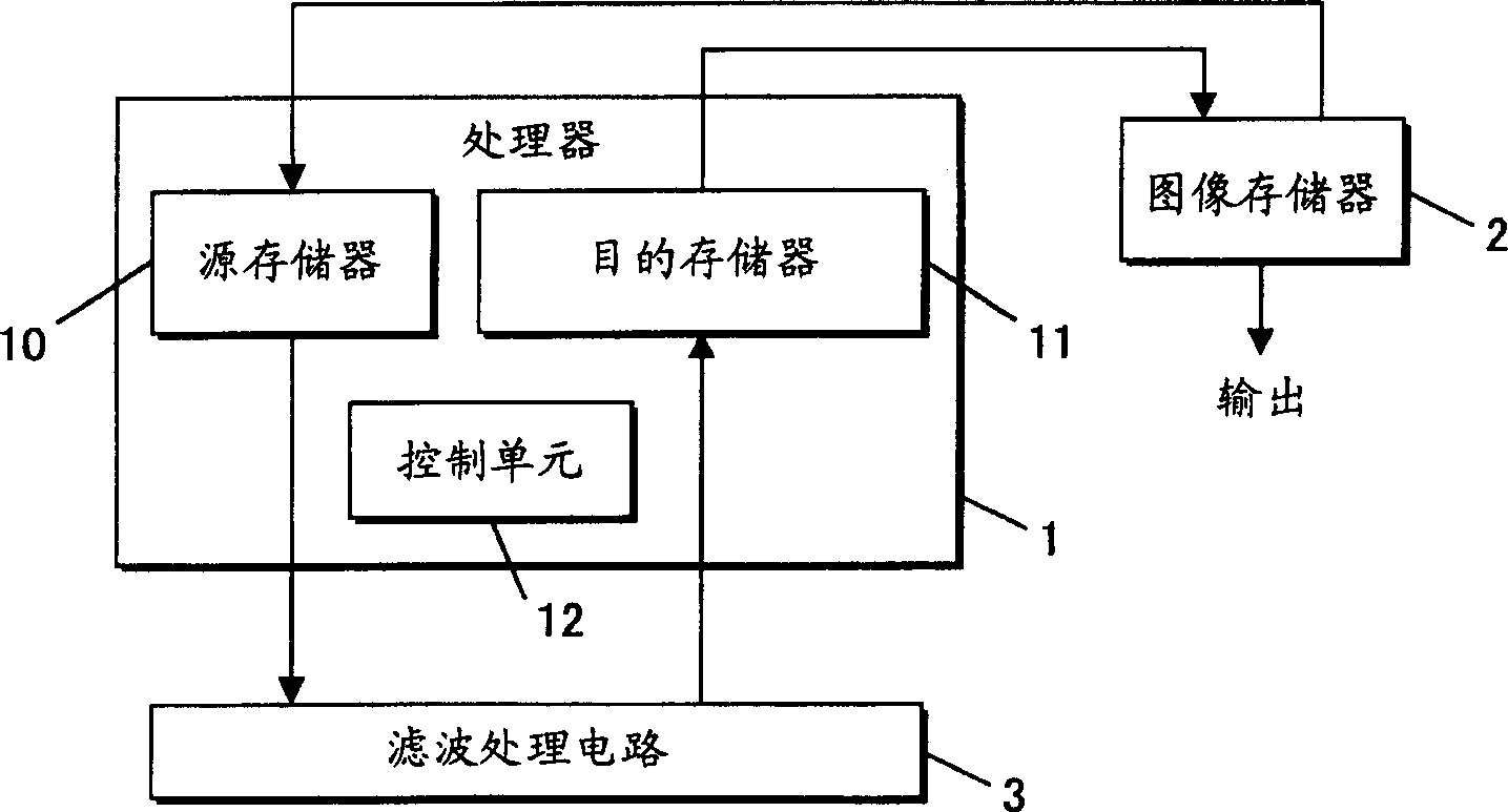
[0119] figure 1 is a block diagram of the image processing device according to Embodiment 1 of the present invention.
[0120] Such as figure 1 As shown, the image processing device includes a processor 1 , an image memory 2 , and a filter processing circuit 3 .
[0121] The processor 1 includes a source memory 10 , a destination memory 11 , and a control unit 12 .
[0122] Next, the overall operation will be briefly described.
[0123] Processor 1 reads encoded image data stored in image memory 2 into source memory 10 .
[0124] The processor 1 performs decoding processing on the image data read into the source memory 10 .
[0125] The processor 1 stores the decoded image data in the destination memory 11 and then transfers it to the image memory 2 .
[0126] In this way, filtering processing is performed on the decoded image data transferred to the image memory 2 .
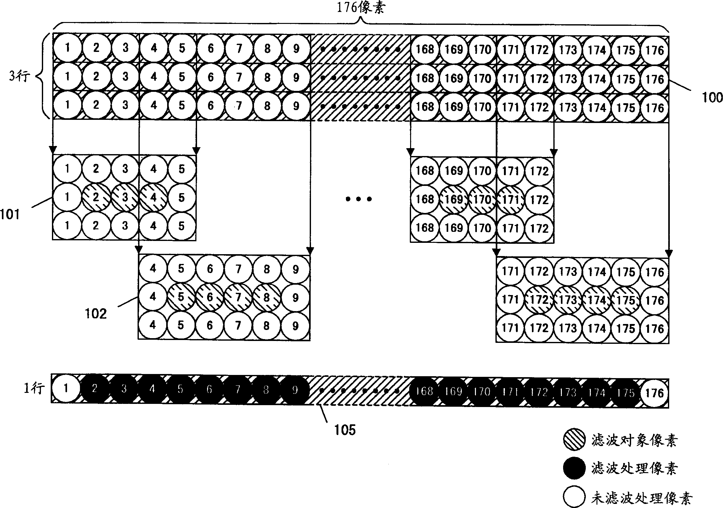
[0127] When performing the filtering process, the image data of 3 lines×176 pixels is divided accordi...
Embodiment approach 2
[0245] The image processing device according to Embodiment 2 of the present invention is provided with a filter processing circuit 4 described below instead of figure 1 The filter processing circuit 3. Other configurations of the image processing device of Embodiment 2 and figure 1 The image processing device is the same.
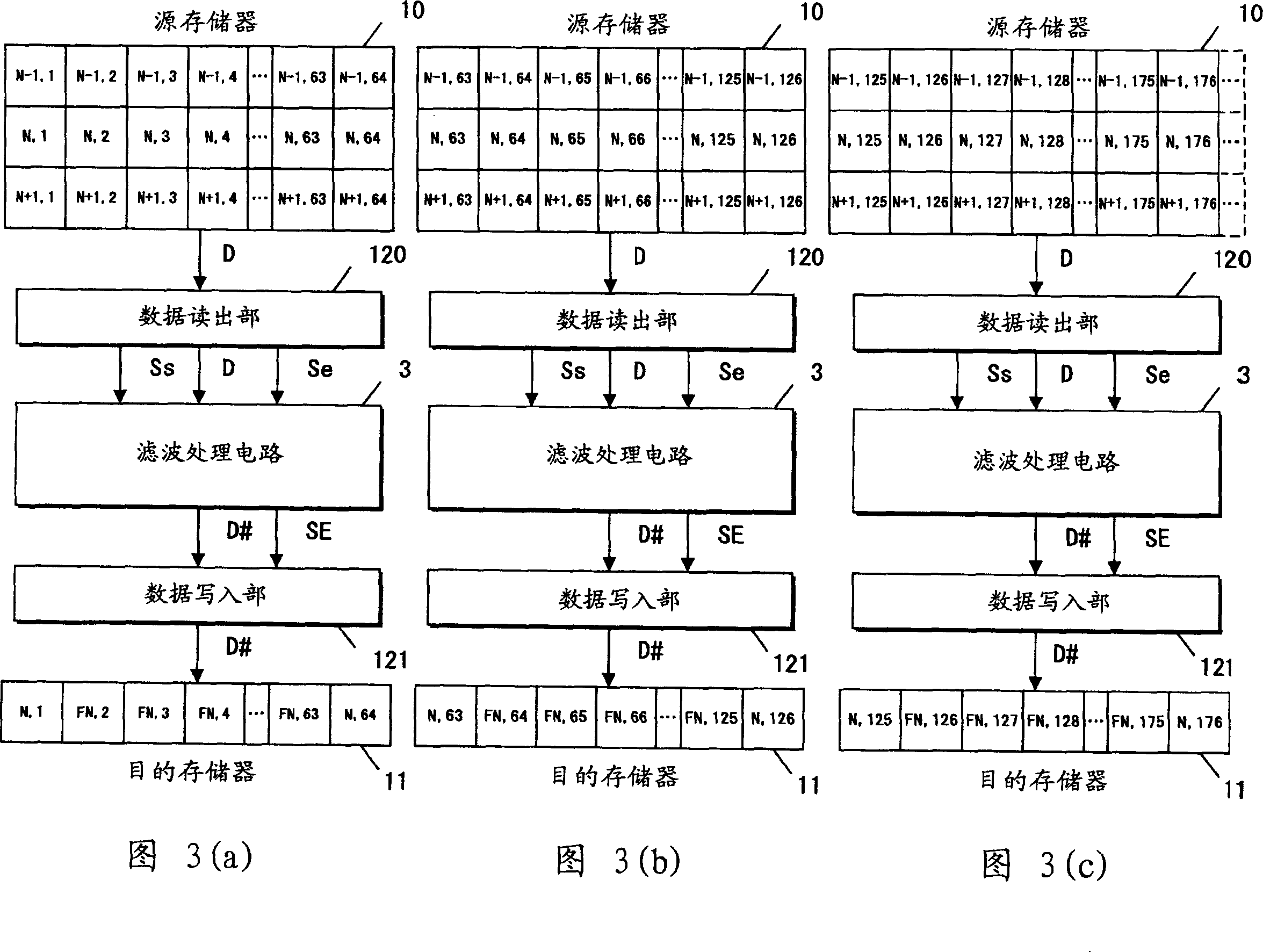
[0246] Figure 8(a) ~ Figure 8(c) is a diagram showing a processing flow when filtering processing is performed. Fig. 8 (a) is a diagram showing the processing flow when performing the first filtering process, Fig. 8 (b) is a diagram showing the processing flow when performing the second filtering process, and Fig. 8 (c) is a diagram showing the processing flow when performing the third filtering process. A diagram of the processing flow at the time of the secondary filtering processing. Again, in Figure 8, for the figure 1 The same parts are attached with the same reference numerals.
[0247] Figure 9 is a block diagram of the filter processing ...
Embodiment approach 3
[0334] The image processing apparatus according to Embodiment 3 of the present invention is provided with a filter processing circuit 5 described below instead of figure 1 The filter processing circuit 3. Other configurations of the image processing device of Embodiment 3 and figure 1 The image processing device is the same.
[0335] Figure 15 It is a block diagram of the filter processing circuit 5 according to the third embodiment. Such as Figure 15 As shown, the filter processing circuit 5 except Figure 9 In addition to the structure of the filter processing circuit 4, a pixel holding buffer 50, selectors 52, 53, and a selector controller 51 are provided.
[0336] The filtering processing will be briefly described below.
[0337] FIG. 16 is a conceptual diagram of filtering processing performed by the image processing device according to Embodiment 3. FIG. Again, the notation in Figure 16 is the same as figure 2 The notation in is the same.
[0338] As shown ...
PUM
 Abstract
Description
Claims
Application Information
 - R&D
- Intellectual Property
- Life Sciences
- Materials
- Tech Scout
- Unparalleled Data Quality
- Higher Quality Content
- 60% Fewer Hallucinations
Browse by: Latest US Patents, China's latest patents, Technical Efficacy Thesaurus, Application Domain, Technology Topic, Popular Technical Reports.
© 2025 PatSnap. All rights reserved.Legal|Privacy policy|Modern Slavery Act Transparency Statement|Sitemap|About US| Contact US: help@patsnap.com