Device for the stepwise transport of liquid utilizing capillary forces

A technology of transmission equipment and capillary tubes, which is applied in the direction of laboratory containers, analytical materials, fluid controllers, etc., and can solve problems such as limited applications

Active Publication Date: 2004-06-02
BOEHRINGER INGELHEIM MICROPARTS
View PDF7 Cites 19 Cited by
  • Summary
  • Abstract
  • Description
  • Claims
  • Application Information

AI Technical Summary

Problems solved by technology

Due to the lack of a gravitational element to initiate the liquid flow, there is no liquid transfer when the substrate is horizontal, so this limits the application of the system

Method used


Image

  • Device for the stepwise transport of liquid utilizing capillary forces
  • Device for the stepwise transport of liquid utilizing capillary forces
  • Device for the stepwise transport of liquid utilizing capillary forces

Examples


Embodiment Construction

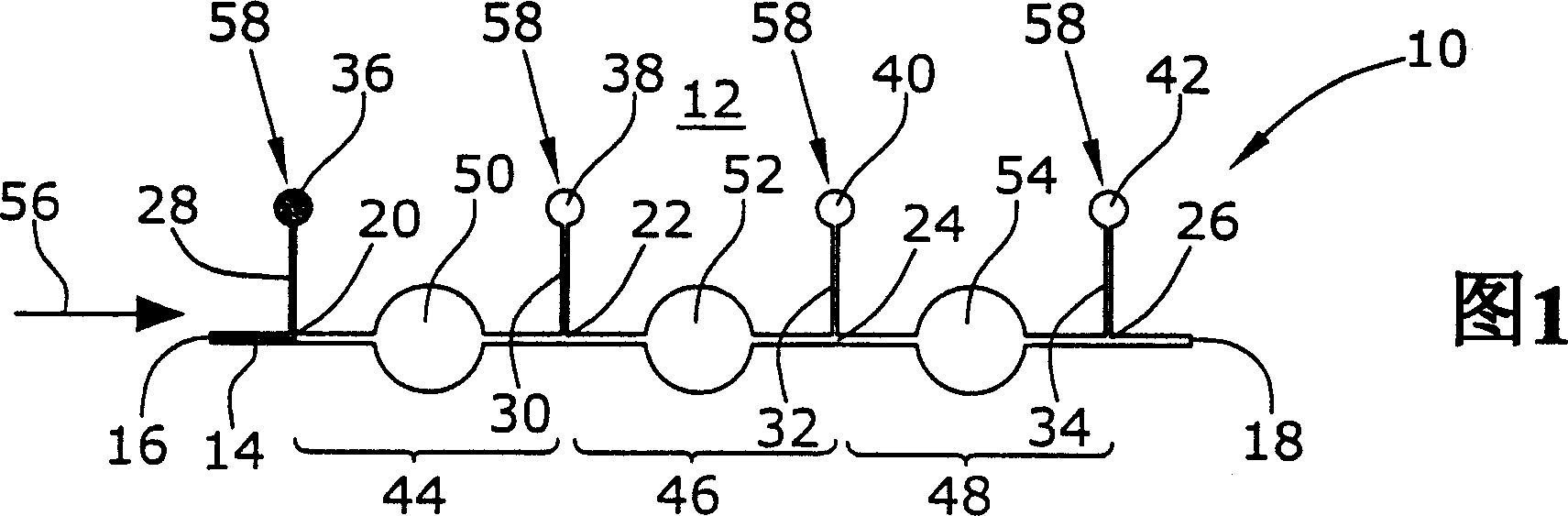
[0028] Figure 1 shows the basic structure of a capillary tubing system 10 according to the invention. Capillary tubing 10 is formed in a substrate 12 (plastic substrate, etc.) and includes conduit 14 including an inlet 16 and an outlet 18 in fluid communication with a container not shown. The liquid in the conduit 14 is transported in the conduit by capillary force.

[0029] Conduit 14 includes several connection points 20, 22, 24 and 26 (four in this embodiment) from which branch off exhaust pipes 28 terminating in exhaust holes 36, 38, 40 and 42, 30, 32 and 34. Conduit 14 is divided by connection points 20 , 22 , 24 and 26 into separate conduit sections 44 , 46 and 48 ; in each conduit section 44 , 46 and 48 there is a reaction chamber 50 , 52 and 54 .

[0030] The capillary tubing system 10 shown in FIG. 1 can be selectively filled with liquid as described below.

[0031] In the initial state, all vent holes 36, 38, 40 and 42 of duct 14 and outlet 18 are closed. If the fi...


PUM


Abstract

The device (10) for the stepwise transport of liquid, particularly of sample liquid to be analyzed, through several reaction chambers located in series in terms of flow while utilizing capillary forces comprises at least one channel (14) through which liquid is transportable on the basis of capillary forces. Further, the device (10) comprises at least two closed vent holes (38,40,42) which are in fluid communication with the channel (14) at connection sites (22,24,26) spaced from each other along the channel (14). The connection sites (22,24,26) divide the channel (14) into several channel sections (44,46,48). The fluid connections between a respective channel section (44,46,48) and the vent holes (38,40,42) allocated thereto can be opened separately.

Description

technical field [0001] The present invention relates to a step-by-step transport device for utilizing capillary force to pass a liquid, preferably a sample liquid to be analyzed, through several flow chambers arranged in series along the flow direction. Background technique [0002] In many different fields of application in analytics and diagnostics, it is necessary to analyze sample fluids. Assays thus performed sometimes require successive exposure of the sample fluid to different reagents. For the automated operation of these assays, it is convenient to transport the sample fluid to be analyzed in a step-by-step manner. [0003] In the prior art it is mainly known to induce liquid flow through the duct and to fill the chamber by evacuating the air in the duct and chamber respectively, thereby creating a liquid flow. Examples of such selective liquid flow mechanisms are found in International Patent No. 99 / 46045, International Patent No. 01 / 64344, U.S. Patent No. 4,849,...

Claims


Application Information

Patent Timeline
Patent Type & Authority Applications(China)
IPC IPC(8): G01N35/08B01L3/00G01N37/00
CPCB01L2400/0694B01L2300/0864B01L2300/044B01L2400/0688B01L2400/0406B01L2300/087B01L2400/0677B01L3/502738B01L2200/0621B01L3/50273
Inventor 格特·布兰肯施泰因拉尔夫·彼得·彼得斯
Owner BOEHRINGER INGELHEIM MICROPARTS
Why Eureka
Try Eureka