

Electromagnetic relay
A technology of electromagnetic relays and electromagnets, applied in the direction of electromagnetic relays, electromagnetic relay details, relays, etc., can solve the problems of poor thermal conductivity, low tightness, and limited heat dissipation of electromagnetic relays, and achieve high thermal conductivity and productivity High and maintain productivity effect
- Summary
- Abstract
- Description
- Claims
- Application Information
AI Technical Summary
Problems solved by technology
Method used
Image

Examples
Embodiment Construction
[0031] Hereinafter, an example of embodiment of the present invention will be described based on the drawings.
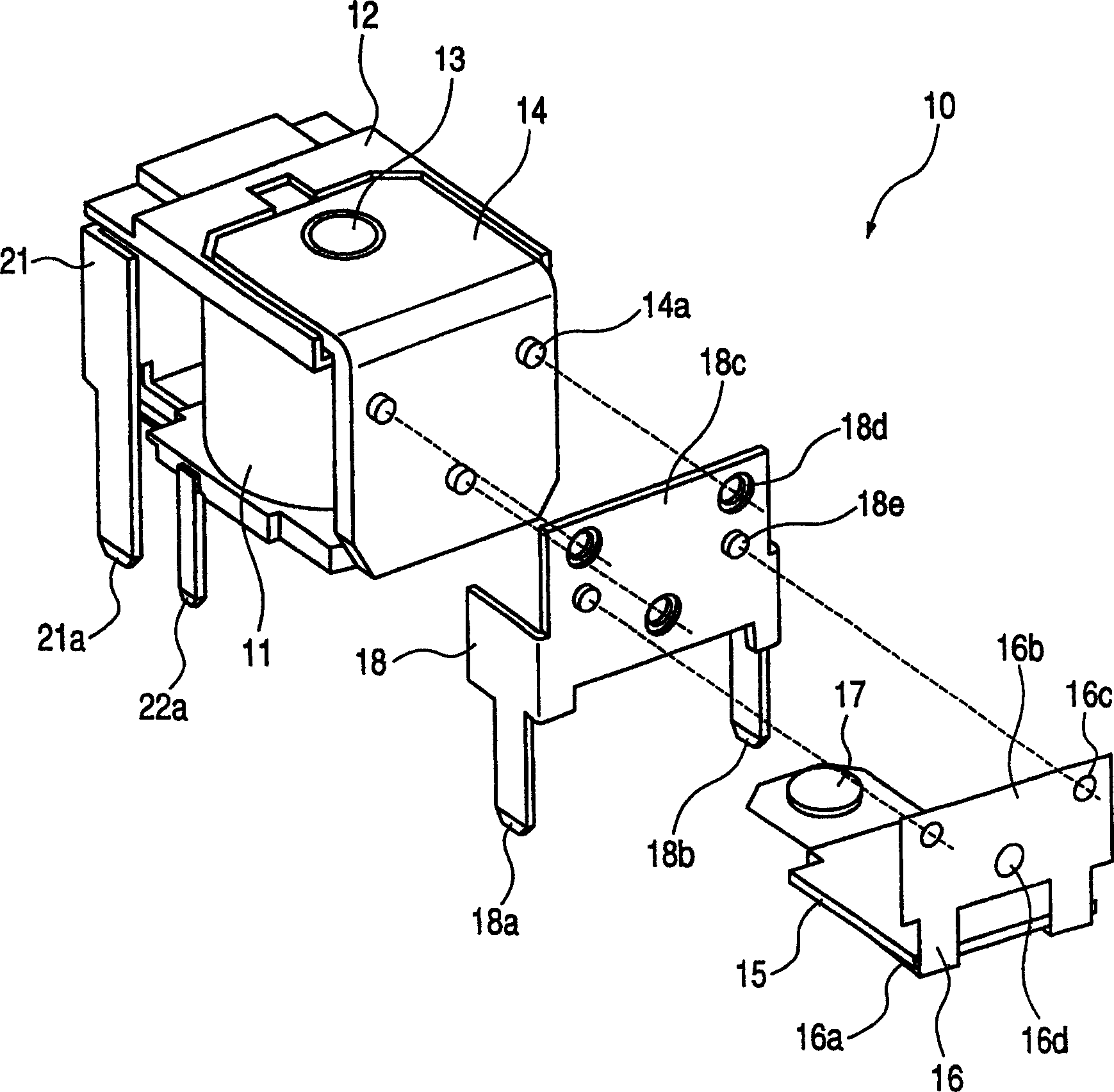
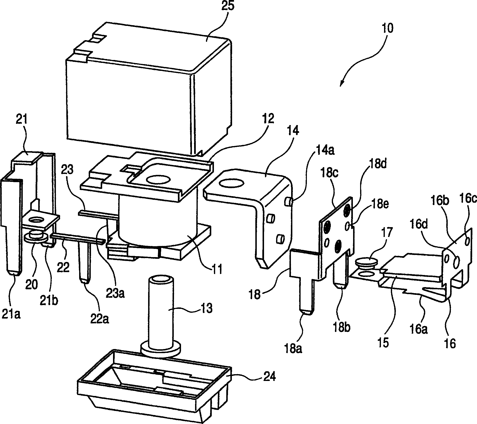
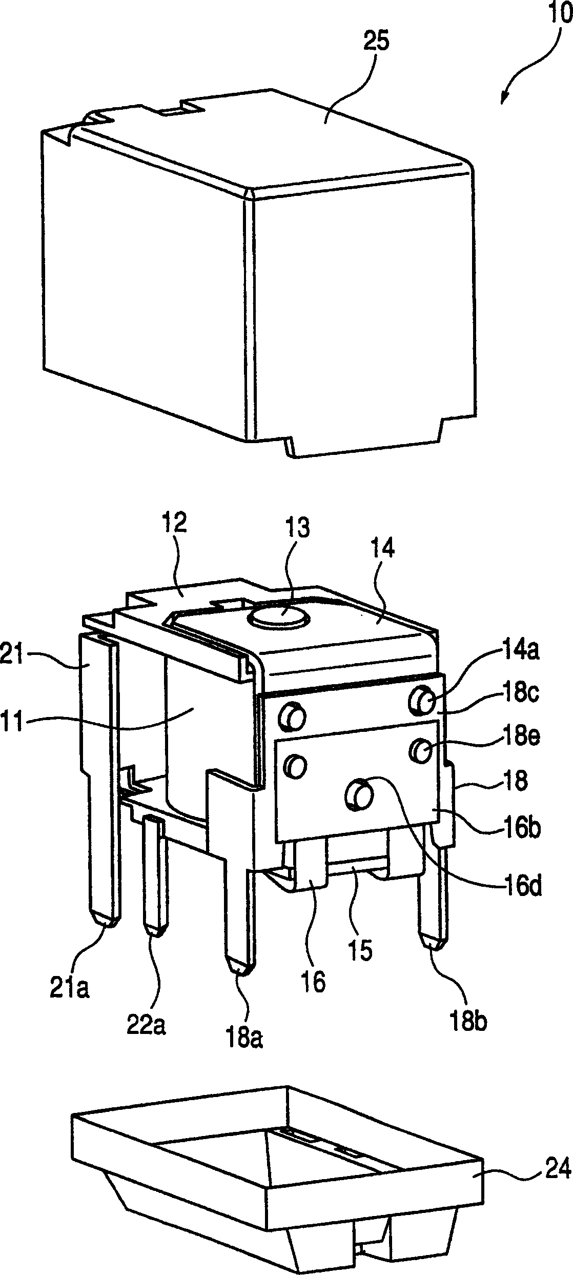
[0032] figure 1 It is a perspective view of the electromagnetic relay 10 of this example (the state before the movable contact terminal 18 etc. which will be described later is mounted), figure 2 is an exploded perspective view of the electromagnetic relay 10 . also, image 3 4 is a perspective view of electromagnetic relay 10 (a state before attachment of case 25 , which will be described later), and FIG. 4 is a view showing a caulking structure for attaching movable contact terminal 18 to case 14 , which will be described later.
[0033] Have again, the shell 25 opening side ( image 3 etc.) is referred to as the housing opening side, the lower end side or the lower side, and the opposite side is referred to as the housing inner side, the upper end side or the upper side.
[0034] Electromagnetic relay 10 such as figure 2As shown, it includes: a bobbin 12 f...
PUM
 Abstract
Description
Claims
Application Information