Washing machine

A washing machine and liquid storage pipe technology, applied in the field of washing machines, can solve the problems of limited effect, inability to completely suppress eccentricity, limited water volume, etc., and achieve excellent vibration reduction effect

Inactive Publication Date: 2004-06-30
SANYO ELECTRIC CO LTD
View PDF0 Cites 10 Cited by
  • Summary
  • Abstract
  • Description
  • Claims
  • Application Information

AI Technical Summary

Problems solved by technology

This encounters the problem that the amount of water that can be contained in the reservoir is limited and thus has a limited effect on balancing the eccentric load
[0005] In addition, if Figure 10 As shown in , if the laundry S is placed towards the open end of

Method used


Image

  • Washing machine
  • Washing machine
  • Washing machine

Examples


Embodiment 1

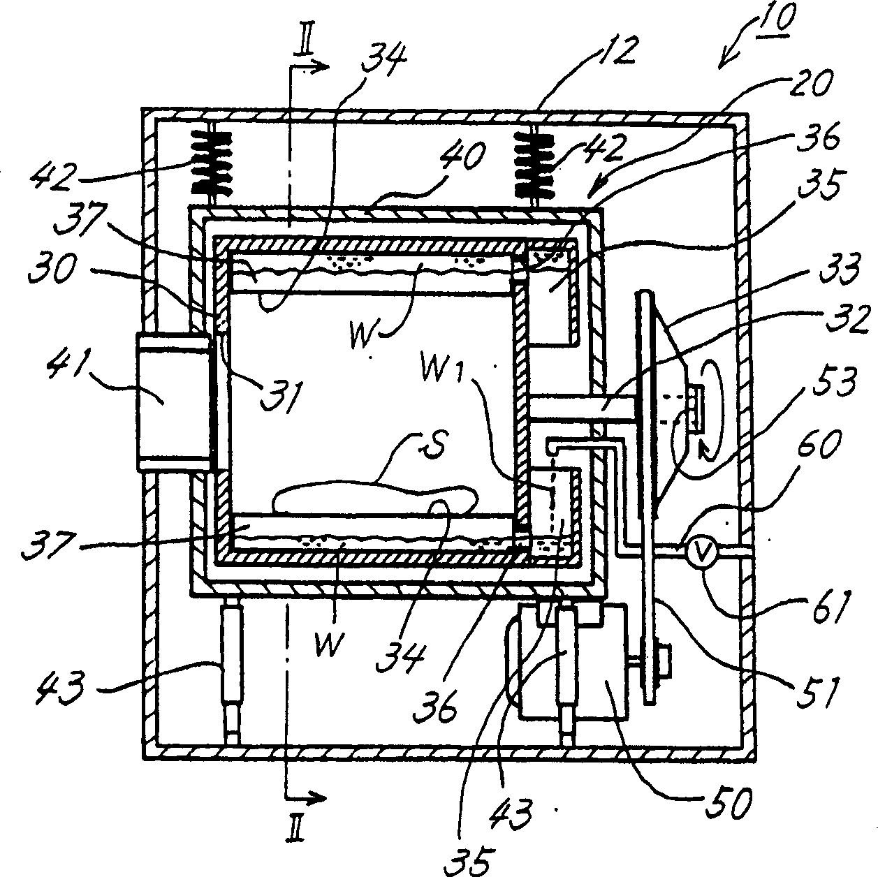
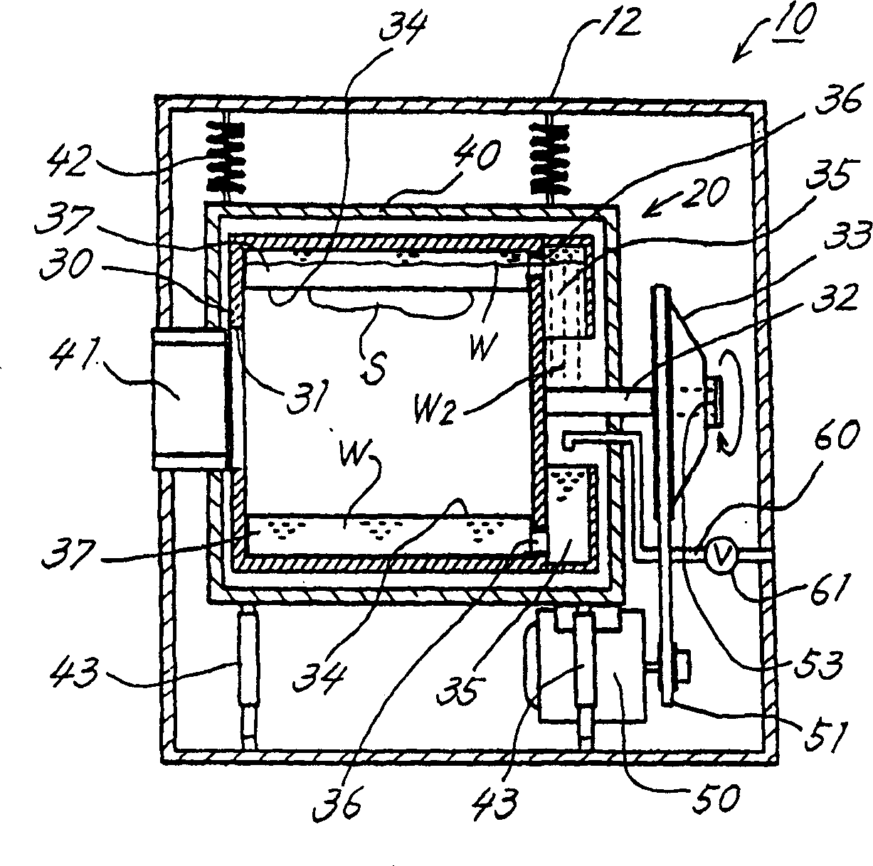
[0023] The following will refer to figure 1 and figure 2 The washing machine 10 of the present invention is described.

[0024] figure 1 is a sectional side view showing the overall structure of the washing machine 10 of the present invention. The washing machine 10 of the present invention includes a cabinet 12 serving as a sealed frame and a washing tub 20 accommodated in the cabinet for washing and rinsing laundry and dehydrating.

[0025] The washing tub 20 includes an inner tub 30 for placing laundry therein, and an outer tub 40 for sealing the inner tub 30 therein.

[0026] The inner tub 30 has an opening 31 formed in one end thereof for placing laundry therethrough, and a closing wall at the other end thereof. The axis of rotation 32 is attached to the outside of the closure wall in a central manner thereof. An inner tub having an opening through which laundry is placed in the tub is formed in its peripheral wall and closed at opposite ends thereof is also avail...

Embodiment 2

[0055] Another embodiment of the liquid storage tube 37 will be described below.

[0056] refer to Figure 5 and Figure 6 In this embodiment, the liquid storage tube 37 is inclined such that its end facing the closed end wall of the inner tub 30 is arranged closer to the axis of the tub 30 . Corresponding to the inclination of the tube 37 , the baffle 34 is also inclined in such a way that its end facing the end wall of the closed tub is arranged closer to the axis of the tub 30 .

[0057] Therefore, one end of the pipe 37 formed with the water passage hole 36 is arranged closer to the shaft of the tub 30 so that liquid can flow into and out of the liquid storage pipe 37 efficiently. Therefore, compared with the case of Embodiment 1, the adjustment to bring the tub 30 to the gravitational balance can be performed in a shorter time.

Embodiment 3

[0059] The liquid storage tank 35 having a desired shape and a water passage hole 36 of a preferred shape will be described below.

[0060] *The shape of the tank

[0061] As shown in FIG. 7 , the reservoir 35 may be constructed such that it tapers toward the axis of the barrel 30 . The opening 35a of the tank is preferably partly provided with a cover 35b in order to prevent excessive water from falling out of the tank 35 . It is preferable to arrange the cover 35b toward the rotation direction of the tub 30, and the cover may be, for example, L-shaped.

[0062] Also as shown in FIG. 7, the opening of the reservoir tank 35 is provided with a cutout 35c so that the tank 35 can drain water with improved efficiency.

[0063] *The shape of the channel hole

[0064] Referring to FIG. 7, a water channel hole 36 for communication between a liquid storage tank 35 and a pipe 37 may be provided through a pipe member 37a.

[0065] FIG. 8 shows the liquid storage tube 37 having one e...


PUM


Abstract

The invention provides a washing machine (10) operable even in the presence of a great eccentric load and exhibiting an outstanding vibration attenuating effect by suppressing eccentricity even if laundry in a drum (30) is in an unbalanced position. The washing machine (10) comprises an inner drum (30) having a rotatably supported axis and a closed wall at at least one end thereof, and a plurality of liquid holding boxes (35) provided on the closed wall of the inner drum (30) externally thereof and each having an opening facing toward the axis. The periphery of the inner drum (30) is provided with hollow liquid holding tubes (37) communicating with the respective liquid holding boxes (35).

Description

field of invention [0001] The present invention relates to a washing machine capable of suppressing vibration of a tub caused by an unbalanced state of laundry to be washed. Background technique [0002] In a washing machine in which an inner tub for placing laundry is arranged to face a horizontal direction, the tub is rotatable for spinning with the laundry inside the tub in an unbalanced state due to centrifugal force. The inner barrel then loses balance under gravity, causing vibration or noise as the barrel rotates. [0003] Therefore, proposed such a washing machine 10, as Figure 10 As shown in , wherein the inner barrel 30 is equipped with a plurality of liquid storage tanks 35, 35 on its closed wall. The washing machine 10 has a water pipe 60 for supplying tap water to the liquid storage tank 35, and water is supplied into the liquid storage tank 35 through the water pipe 60 in order to change the amount of water held in the tank 35 according to the eccentricity of...

Claims


Application Information

Patent Timeline
IPC IPC(8): D06F37/20D06F23/02D06F25/00D06F37/04D06F37/22D06F49/06
CPCD06F37/04D06F37/225D06F34/16
Inventor 纪之内隆生山本宏横井康彦园田泰亮
Owner SANYO ELECTRIC CO LTD
Why Eureka
Try Eureka