Cooling device

A technology of cooling device and refrigerant, which is applied in the direction of cooling fluid circulation device, household refrigeration device, cooler, etc. It can solve the problems of time-consuming installation position balance, complicated installation engineering, and cooling capacity, etc., so as to reduce power consumption , Reduce the effect of reducing the simplification of the installation process and reducing the number of installation devices

Inactive Publication Date: 2004-07-07
MITSUBISHI ELECTRIC CORP
View PDF1 Cites 11 Cited by
  • Summary
  • Abstract
  • Description
  • Claims
  • Application Information

AI Technical Summary

Problems solved by technology

In this way, since there are devices that should be installed in the same position, it takes time to balance the installation position when analyzing how to install it to have an effect on the system.
In addition, there is a problem of poor appearance due to unevenness due to the installation of multiple devices outside the box
[0011] In addition, the installation process of the conventional cooling device was complicated due to the large number of devices. In particular, since the auxiliary cooling device adopts the natural circulation method of the refrigerant, the refrigerant piping connecting the outdoor unit and the indoor unit should be appropriately sloped (ratio) If the piping process is implemented, there is a problem that the cooling capacity cannot be exerted

Method used


Image

  • Cooling device
  • Cooling device
  • Cooling device

Examples


Embodiment Construction

[0037] Embodiments of the present invention will be described below with reference to the drawings as an example of a cooling device for cooling the inside of a storage box for storing equipment including heat generating elements.

[0038] Implementation form 1

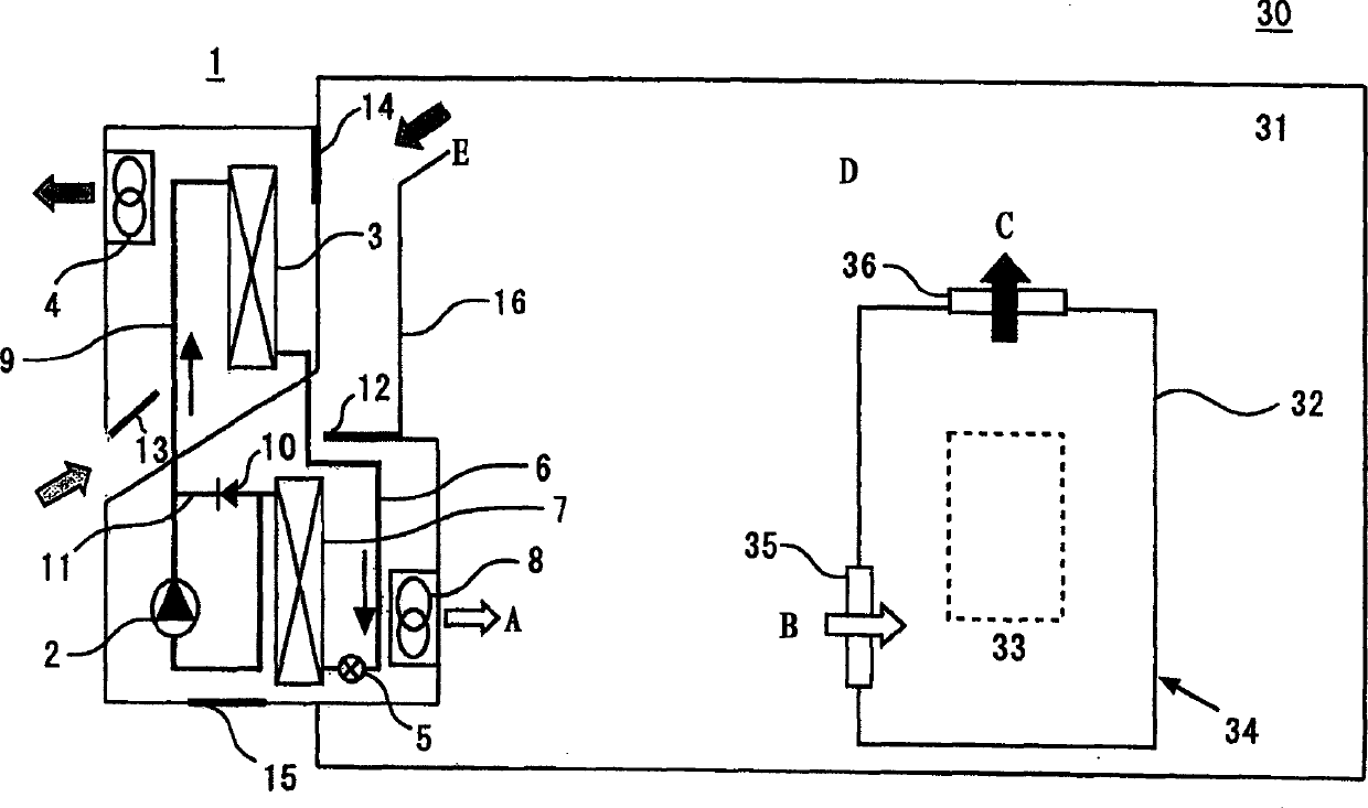
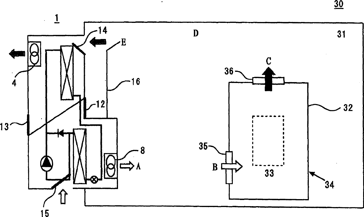
[0039] Fig. 1, Fig. 2 are the schematic configuration diagrams showing the cooling device of Embodiment 1 of the present invention, Fig. 1 is the operating state when the refrigerant is forced to circulate and when the refrigerant is naturally circulated, that is, when it is not ventilated, and Fig. 2 shows the operation state when it is ventilated operating status.

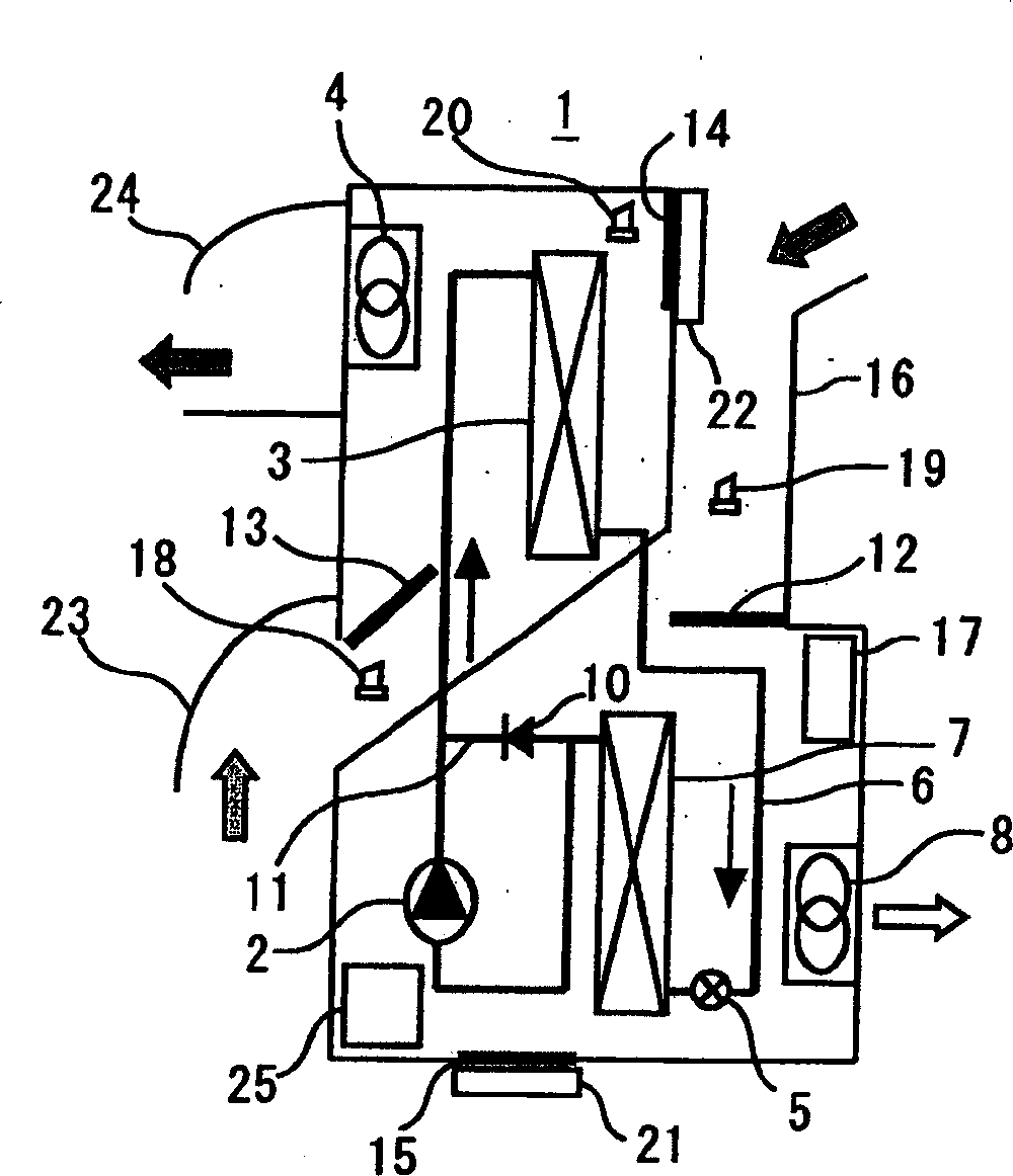
[0040] In each figure, the reference numeral 1 is a cooling device, the reference numeral 2 is a compressor, the reference numeral 3 is a condenser, the reference numeral 4 is an outdoor fan, the reference numeral 5 is an expansion valve such as an electronic expansion valve, the reference numeral 6 is a liquid piping, and the reference numeral 7 is an e...


PUM


Abstract

A cooling system of the invention has heat exchange means which is housed in one enclosure (31) and is constituted of a plurality of heat exchange modes, and the heat exchange means includes a refrigerant forced circulation mode, a refrigerant natural circulation mode, and a ventilation mode. Temperature detection means performs switching to an optimal mode, to thereby cool the inside of the enclosure (31) of a housing (30) accommodating equipment (32) including a heat-generating component (33).

Description

technical field [0001] The present invention relates to a cooling device, in particular to a cooling device in a housing box of a heat generating device containing a sensible heat generating body such as a built-in substrate. Background technique [0002] The storage box to be cooled generally stores heat-generating equipment in a closed box, but sometimes the box is so narrow that no one can enter, and the equipment inside has heat-generating components and is moderately cooled. [0003] As a cooling device for cooling such a case, there is a device described in JP-A-2001-041503. The cooling device is shown in Figure 9. [0004] In Fig. 9, the box body cooling system 51 of the storage box 52 is composed of an auxiliary cooling device indoor unit 59 closed by a natural circulation refrigerant circuit 65, an auxiliary cooling device outdoor unit 60, and a main cooling device indoor unit closed by a forced circulation refrigerant circuit 66. 61. The main cooling device is co...

Claims


Application Information

Patent Timeline
Patent Type & Authority Applications(China)
IPC IPC(8): F25D31/00F25D19/02H05K7/20
CPCF25D2700/12F25D19/02H05K7/20609F25D2700/14F24F1/022F25D31/00
Inventor 龟山晋瀬下裕畑村康文井野正兴小早川浩之榎本寿彦齐藤信
Owner MITSUBISHI ELECTRIC CORP
Why Eureka
Try Eureka