Roll conveyer

A conveyor and roller technology, applied in the direction of conveyors, conveyor objects, rollers, etc., can solve problems such as scratches, low substrate strength, and easy damage

Inactive Publication Date: 2004-07-21
MARUYASU KIKAI KK
View PDF3 Cites 32 Cited by
  • Summary
  • Abstract
  • Description
  • Claims
  • Application Information

AI Technical Summary

Problems solved by technology

However, due to the low strength of the substrate of the liquid crystal display panel or the plasma display panel, it is easy to be damaged, so the central part of the substrate is sometimes scratched due to contact with the above-mentioned central roller, and even the expensive substrate becomes a defective product.

Method used


Image

  • Roll conveyer
  • Roll conveyer
  • Roll conveyer

Examples


Embodiment Construction

[0030] An embodiment of the present invention will be described below with reference to the drawings.

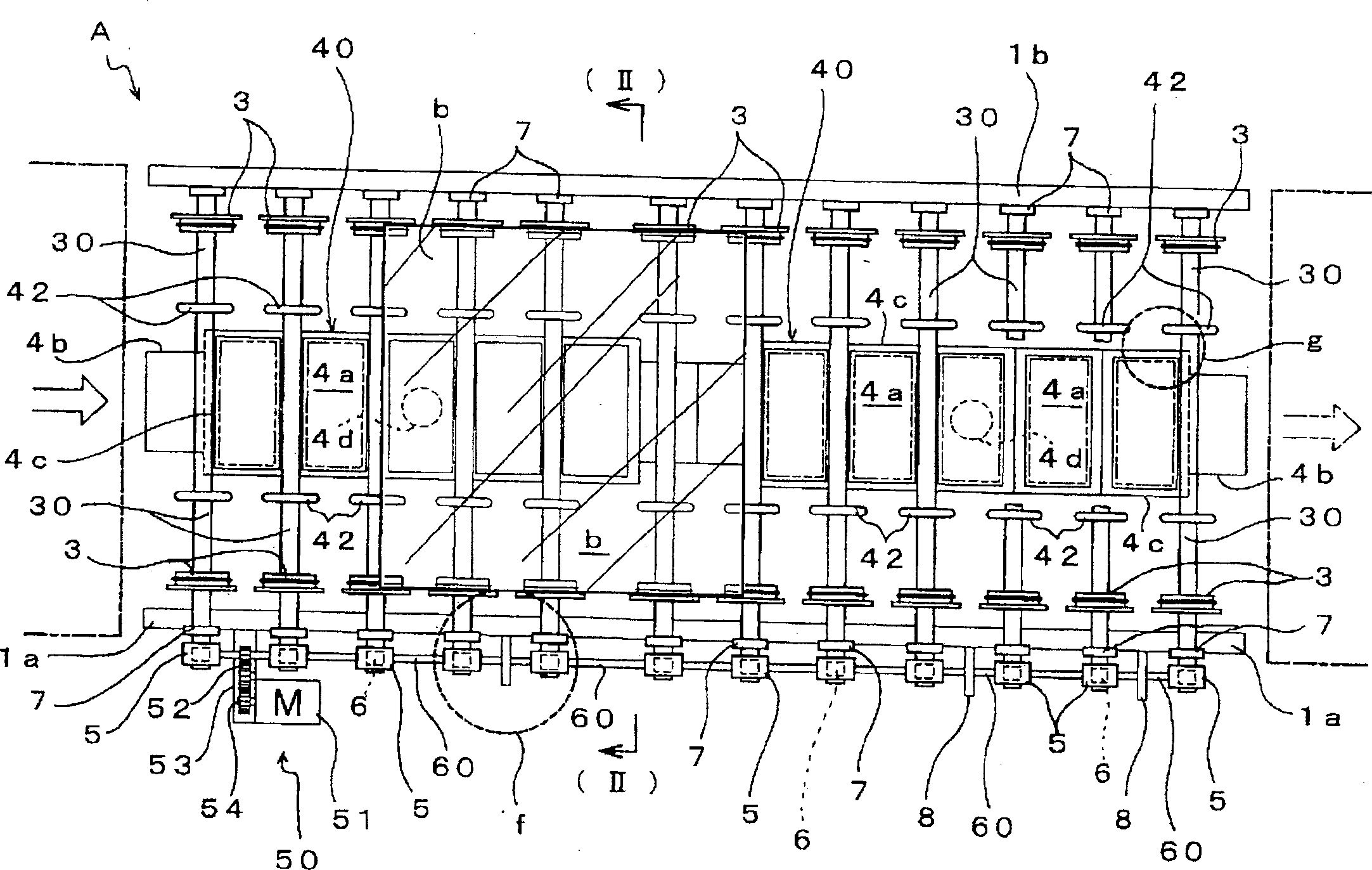
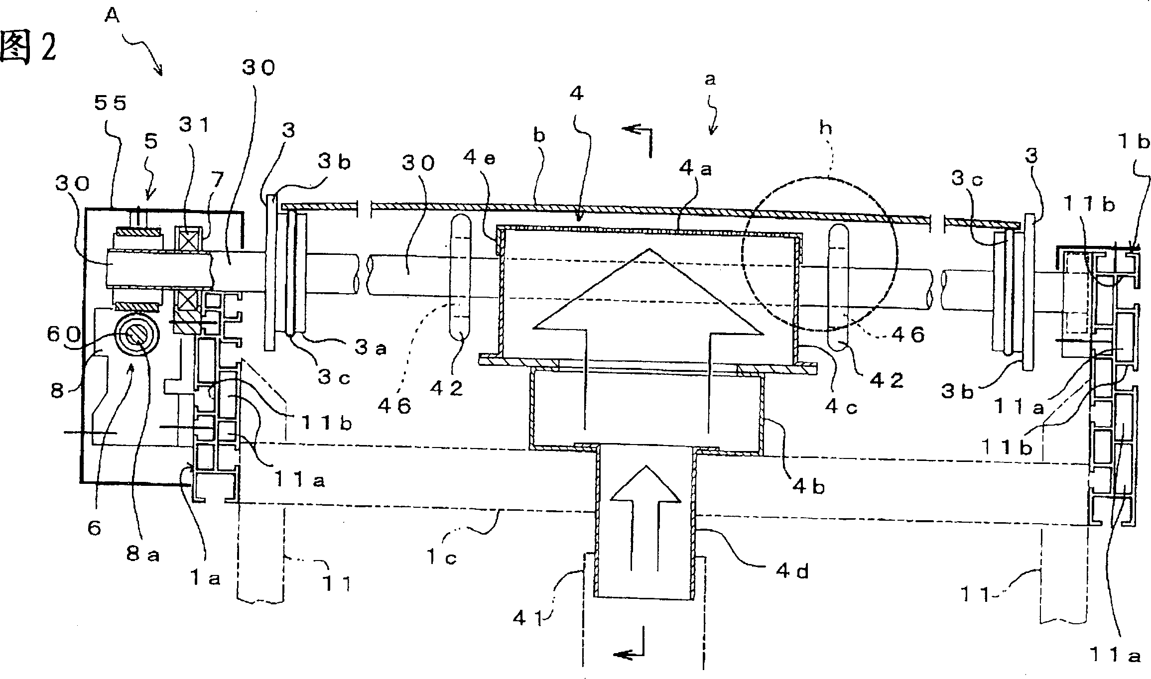
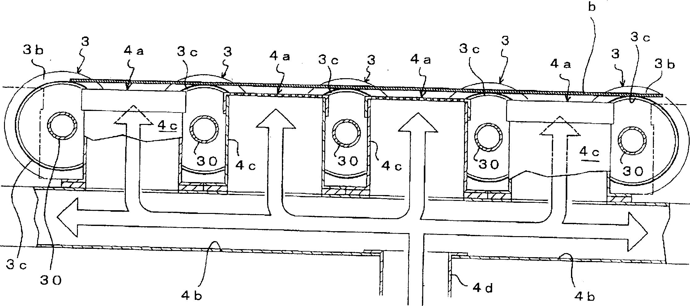
[0031] Figure 1 to Figure 3 Roller conveyor A embodying the invention is shown. This roller conveyor A has two left and right frames 1a, 1b supported by legs 11, and a support shaft 30 on which the rolling rollers 3 are mounted is provided between the frames 1a, 1b.

[0032] The left and right frames 1a, 1b are elongated plate-shaped bodies formed by extruding aluminum, as shown in the cross-sectional view of Figure 2, hollowed out to form a hollow part 11a and gaps for inserting bolts, nuts, fixing parts, etc. Groove 11b etc. Between the lower parts of these frames 1a, 1b, a connecting rod 1c is horizontally provided to connect the left and right frames 1a, 1b.

[0033] The roller conveyor A of this embodiment is a mechanism for conveying panels with a width of approximately 700mm to 800mm and 1200mm to 1500mm, and it conveys substrates such as liquid crystal display pa...


PUM


Abstract

Rotary rollers 3 are provided at both the left and right ends of each support shaft 30, and are arranged side by side to compose a conveyance path (a). An air blowoff path 4 is arranged at the middle section of the conveyance path (a), and is installed over the entire length of the conveyance path (a). The upper surface of the air blowoff path 4 is formed to be a flat, porous surface 4a having breathing properties. Air is jetted out of the upper surface toward the lower surface of a flat object (b) traveling on the porous surface 4a. A thin air layer is created between them. Then, the center section of the flat object (b) is lifted without any contact. More specifically, since the center section of the flat object (b) can be maintained in a non-contact state by a thin air layer, conveyance can be made smooth, and damage such as friction scratches to the flat object (b) can be avoided in a conveyance process.

Description

technical field [0001] The invention relates to a roller conveyor for conveying thin and fragile plate-shaped objects, such as liquid crystal display panels or plasma display panels. Background technique [0002] Figure 11 (a) and (b) are conventional roller conveyors for conveying plate-like objects. This roller conveyor 100 is provided with frames 101 on both left and right sides. Spindle shafts 102 are erected between these racks 101 , and are arranged side by side at appropriate intervals in the conveying direction of the roller conveyor 100 . Rollers 106 are attached to both ends of each support shaft 102 and fixedly support the side edges of the plate, and rotate integrally with the support shaft 102 . [0003] In addition, a center roller 103 having a diameter equal to that of the above-mentioned roller 106 is provided substantially in the center of each of the support shafts 102 , and is rotatable relative to the support shaft 102 . In addition, drive transmissio...

Claims


Application Information

Patent Timeline
Patent Type & Authority Applications(China)
IPC IPC(8): B65G13/00B65G13/06B65G47/30B65G49/06
CPCB65G13/06B65G39/04B65G49/061B65G51/02B65G2201/022G02F1/1303H02K49/102
Inventor 宫坂哲男
Owner MARUYASU KIKAI KK
Why Eureka
Try Eureka