

Amplifier with gain in direct proportion to power voltage
A power supply voltage and amplifier technology, applied in the field of angular velocity sensor devices, can solve the problems of not being able to correctly track the change of power supply voltage Vdd
- Summary
- Abstract
- Description
- Claims
- Application Information
AI Technical Summary
Problems solved by technology
Method used
Image

Examples
no. 1 Embodiment
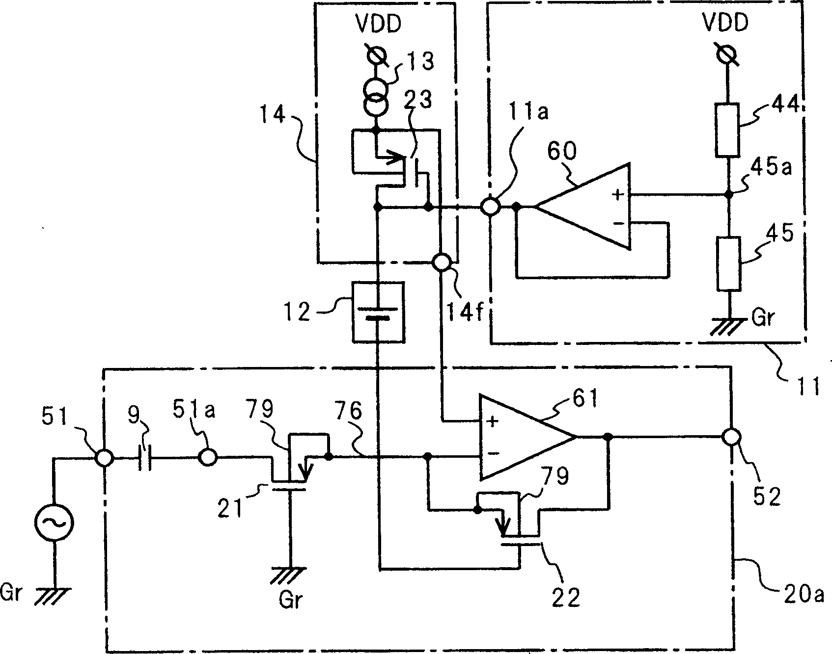
[0050] Refer below Figure 1 to Figure 3 The power supply voltage proportional amplifier of the first embodiment of the present invention will be described.
[0051] exist figure 1 Among them, the power supply voltage proportional amplifier of the first embodiment includes an amplifying circuit 20a for amplifying and outputting an input signal, a bias circuit 11 as a first voltage source, a constant voltage source 12 as a third voltage source, and a circuit as a second voltage source. Bias circuit 14. The bias circuit 11 outputs a positive voltage obtained by dividing the power supply voltage Vdd to the output terminal 11a. In the amplifier circuit 20a, the input terminal 51 is connected to the drain of a first MOS type field effect transistor (hereinafter abbreviated as MOS-FET) 21 of the P-channel via a capacitor 9 for blocking direct current. When the input signal applied to the input terminal 51 does not contain a DC component, the input signal may be input to the inpu...
no. 2 Embodiment
[0109] Refer below Figure 4 A power supply voltage proportional amplifier according to a second embodiment of the present invention will be described. P-channel MOS-FETs 21, 22, and 23 are used in the power supply voltage proportional amplifier of the first embodiment, but the power supply voltage proportional amplifier of the second embodiment is constructed using N-channel MOS-FETs.
[0110] Such as Figure 4 As shown, in the N-channel MOS-FETs 24, 25, and 26, the gate of the MOS-FET 24 functioning as an input resistor is connected to the power supply VDD. The positive terminal of the constant voltage source 12 (third voltage source) is connected to the gate of the MOS-FET 25 . In the bias circuit 14 a (second voltage source), the source terminal 84 of the MOS-FET 26 is connected to the circuit ground Gr via the constant current source 13 . The output terminal 14g of the bias circuit 14a is connected to the connection point of the above-mentioned source terminal 84 and t...
no. 3 Embodiment
[0116] Next, a power supply voltage proportional amplifier according to a third embodiment of the present invention will be described with reference to the circuit diagram of FIG. 7 . In FIG. 7, since the constant voltage source 12, bias circuits 11 and 14 and figure 1 The cases shown are the same, so repeated explanations are omitted. The amplifying circuit 20d includes: the inverting input terminal (-) is connected to the input terminal 51 through the capacitor 9, and the non-inverting input terminal (+) is connected to the first operational amplifier 64 of the output terminal 14f of the bias circuit 14; and the output terminal is connected to the amplifying circuit The second operational amplifier 65 of the output terminal 52 of 20d. A resistor 46 is connected between the inverting input terminal (−) of the second operational amplifier 65 and the output terminal 52 . The sources of the two P-channel MOS-FETs 31 and 32 are connected in common, and the source 76 thereof is...
PUM
 Abstract
Description
Claims
Application Information