Touch rod holding device, touch rod display device and braille display part
A technology of display device and touch bar, which is applied in the field of braille display components, touch bar display equipment, touch bar holding and moving mechanism, and can solve the problems that continuous display cannot be realized
- Summary
- Abstract
- Description
- Claims
- Application Information
AI Technical Summary
Problems solved by technology
Method used
Image

Examples
Embodiment 1
[0126] figure 1 is a schematic plan view showing a main part of a rotating part for a continuous touch stick display device (Braille display device) according to an embodiment of the present invention, with its upper disk removed. figure 2 From figure 1 A schematic cross-sectional view taken in the S1X-S1Y plane, showing figure 1 The main part of the rotating part, on which the upper disc is fixed. Figure 9 is a schematic oblique view conceptually showing the main part of the touch stick display device according to the embodiment of the present invention. Figure 10 is a schematic floor plan conceptually showing the Figure 9 The main part of the device, which is in the Figure 9 The casing in is removed. Figure 11 yes Figure 10 Schematic side view of the main parts of the device. Figure 12 is a schematic block diagram showing a control circuit for controlling a rotating member drive motor, an actuator, and the like.
[0127] The touch stick display device 400 ...
Embodiment 2
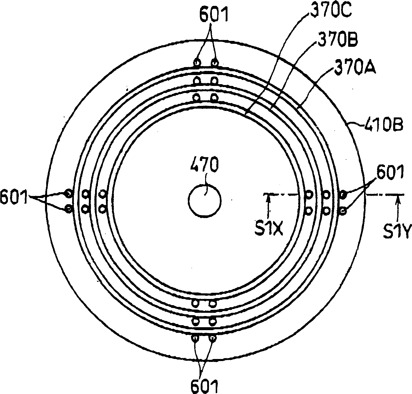
[0174] FIG. 18A schematically shows a touch stick display device (Braille display device) according to an embodiment of the present invention. The touch stick display device 300 includes eight elements. The first element comprises a disc-shaped rotating part 310 having a plurality of perforations arranged in its radial position, separated from each other and present in the main plane of the rotating part (touch surface TS). The second element includes a gear 340 which meshes with the periphery of the rotating part 310 . The third element includes a rotary drive (not shown) for rotating the rotary member 310, the rotary drive including gears, motors and the like. The fourth element includes rods 301, each rod is arranged in each hole, and in the length direction of each hole or each rod between the first position (rod reset position) and the second position (rod display position) between rise and fall.
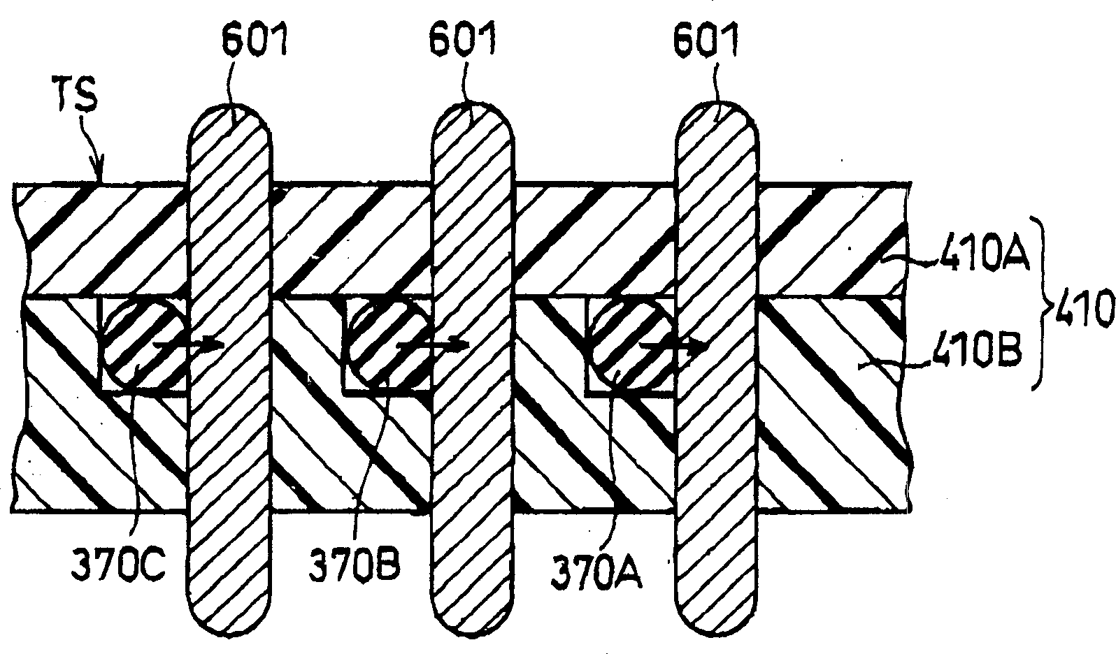
[0175] The fifth element comprises O-rings 370 mounted respectively on ...
Embodiment 3
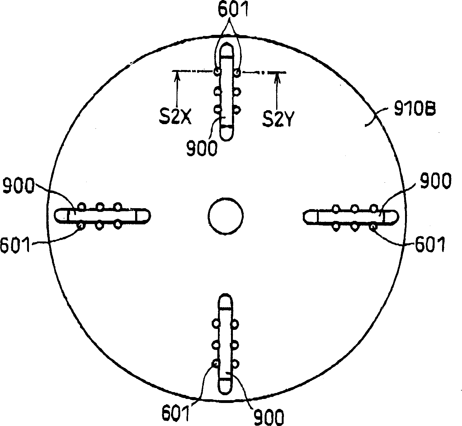
[0197] The touch stick display device (braille display device) displayed in this embodiment is similar to the touch stick display device in Embodiment 2, except that the touch stick holding mechanism or device here is partially different from the touch stick holding mechanism in Embodiment 2 or equipment. More specifically, in this embodiment, the annular member (O-ring) in Embodiment 2 is replaced with an elastic sheet member such as a rubber sheet, which has a plurality of perforations at positions corresponding to the plurality of rods , thereby, the plurality of rods can be collectively and elastically contacted and supported by the elastic sheet member around its ring shape.
[0198] The diameter of each perforation in the elastic sheet member is designed to be about 10 to 30% smaller than the outer diameter of each rod. The elastic sheet (rubber sheet) has a thickness of about 1.2 mm and is made of, for example, NBR (acrylonitrile-butadiene rubber) with a rubber hardnes...
PUM
 Abstract
Description
Claims
Application Information
 - R&D
- Intellectual Property
- Life Sciences
- Materials
- Tech Scout
- Unparalleled Data Quality
- Higher Quality Content
- 60% Fewer Hallucinations
Browse by: Latest US Patents, China's latest patents, Technical Efficacy Thesaurus, Application Domain, Technology Topic, Popular Technical Reports.
© 2025 PatSnap. All rights reserved.Legal|Privacy policy|Modern Slavery Act Transparency Statement|Sitemap|About US| Contact US: help@patsnap.com