Mixed type power generating equipment of cooling type turbine integrated fuel battery

A technology for power generation equipment and fuel cells, which is used in fuel cell combinations, fuel cells, and fuel cell applications, and can solve problems such as reducing equipment thermal efficiency, emissions, and waste of heat content.

Inactive Publication Date: 2004-07-21
GENERAL ELECTRIC CO
View PDF1 Cites 11 Cited by
  • Summary
  • Abstract
  • Description
  • Claims
  • Application Information

AI Technical Summary

Problems solved by technology

When there is no means of burning part of the spent fuel, the heat content of these components is wasted, thus reducing the thermodynamic efficiency of the plant
In addition, unburned hydrocarbons may also be undesirably emitted into the atmosphere when the fuel used in the fuel cell is not fully converted

Method used


Image

  • Mixed type power generating equipment of cooling type turbine integrated fuel battery
  • Mixed type power generating equipment of cooling type turbine integrated fuel battery
  • Mixed type power generating equipment of cooling type turbine integrated fuel battery

Examples


Embodiment Construction

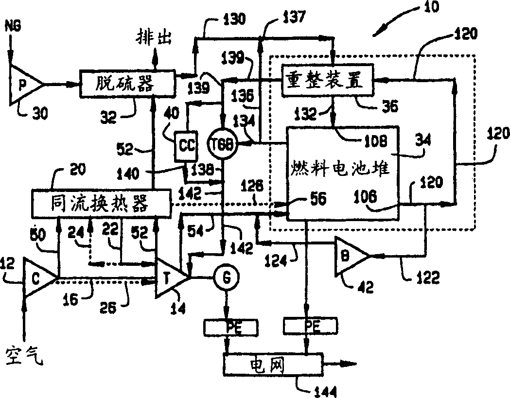
[0018] figure 1 An exemplary combined gas turbine and fuel cell hybrid power plant 10 is schematically illustrated, the power plant 10 including a fuel cell portion and a turbine portion to cooperate with each other to generate electricity. The turbine section includes a compressor 12 , a turbine 14 , a rotor 16 for the turbine 14 to drive the compressor 12 , a generator 18 and a recuperator 20 . The fuel cell part includes a fuel pump 30 , a desulfurizer 32 , a fuel cell stack 34 , a fuel pre-compressor 36 for the fuel cell stack 34 , an exhaust burner 38 , a catalytic chamber 40 and an exhaust blower 42 . As explained in some detail below, while the basic components of device 10 are well known, efficiency improvements over known devices are obtained by strategically interconnecting device components with recirculation flow paths to enhance system performance and efficiency. As will be understood hereinafter, by recirculating the exhausted air and fuel flow from the fuel cel...


PUM


Abstract

A hybrid power plant (10) includes a turbine (14), a compressor (12) driven by the turbine and a recuperator (20) in flow communication with the compressor. The recuperator is configured to transfer heat from turbine exhaust (52) to compressed air, and at least one fuel cell (34) is in flow communication with said recuperator to provide fresh air for said fuel cell.

Description

technical field [0001] The present invention relates generally to power plants and, more particularly, to hybrid power plants including integrated fuel cells. Background technique [0002] In some hybrid power generation systems, fuel cells are combined with conventional gas turbines to increase the amount of power generated (efficiency) in the power plant. Known fuel cells, such as solid oxide fuel cells, include multiple solid fuel cells that react a gaseous fuel, such as reformed natural gas, with air to produce electricity and high temperature gas. The gas turbine compressor supplies air to the fuel cell, which operates at high pressure, and the fuel cell produces high temperature gas for expansion within the turbine. The fuel cell stack exhaust gas is combined with the fuel cell stack exhaust fuel and the resulting thermal emissions are converted successfully in the turbine section of the plant. Therefore, electricity is generated by a solid oxide fuel cell generator ...

Claims


Application Information

Patent Timeline
Patent Type & Authority Applications(China)
IPC IPC(8): F01K23/10F02C6/00F02C6/04F02C7/08H01M8/00H01M8/04H01M8/06H01M8/10H01M8/12H01M8/14H01M8/22H01M8/24H02K7/18
CPCH01M2250/402Y02E20/16H01M2008/147Y02E20/18H01M8/2415H01M8/04007Y02E60/50Y02E60/56H01M2250/40Y02B90/12H01M8/0612H01M8/04097H01M2008/1095H01M8/04111Y02E60/525H01M2008/1293Y02E60/526Y02B90/10H01M8/2484H01M8/04
Inventor R·S·邦克C·巴兰
Owner GENERAL ELECTRIC CO
Why Eureka
Try Eureka