Method for mfg. vortex compressor and its cross ring

A technology for scroll compressors and Oldham rings, applied in the direction of rotary piston machinery, rotary piston/swing piston pump components, mechanical equipment, etc., can solve the problem of sticking, easy wear of sliding parts, and reduce the support structure Lifespan and other issues

Inactive Publication Date: 2004-07-28
PANASONIC CORP
View PDF1 Cites 10 Cited by
  • Summary
  • Abstract
  • Description
  • Claims
  • Application Information

AI Technical Summary

Problems solved by technology

[0011] However, since the compressor using an alternative refrigerant does not contain chlorine, it cannot be expected to have excellent lubricity like the existing specific CFC.
[0012] Therefore, the sliding conditions become severe, and in the support structure using the Oldham ring of the above-mentioned conventional orbiting scroll, the sliding part is prone to wear, thereby reducing the life of the support structure part.
[0013] The reason for this is that the sliding portions of both the Oldham ring of the support structure, the orbiting scroll, and the fixed member tend to b

Method used


Image

  • Method for mfg. vortex compressor and its cross ring
  • Method for mfg. vortex compressor and its cross ring
  • Method for mfg. vortex compressor and its cross ring

Examples


Example Embodiment

[0030] Example 1

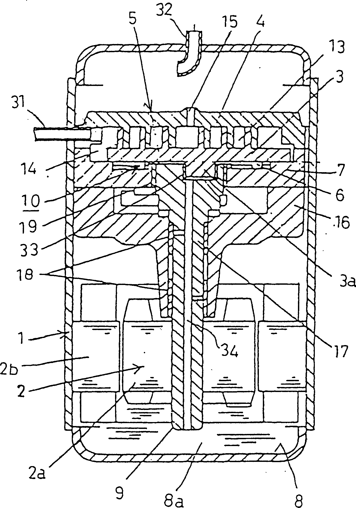
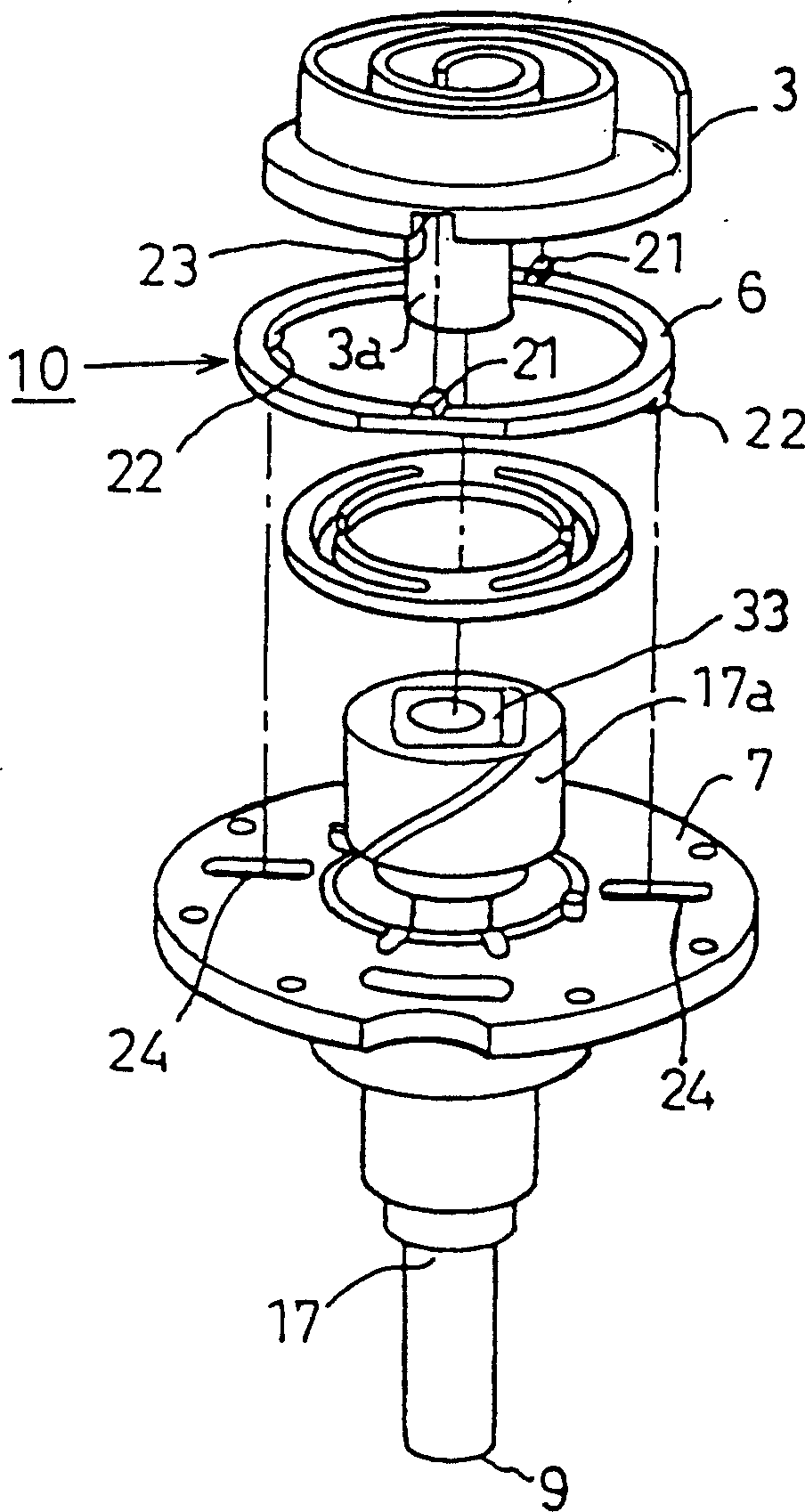
[0031] The first embodiment of the scroll compressor of the present invention is such as Figure 1-Figure 3 shown. This embodiment is a vertical scroll compressor for refrigeration and air conditioning, figure 1 is a longitudinal sectional view of a scroll compressor, figure 2 Yes figure 1 An exploded perspective view of the main parts of the compressor shown, figure 2 Yes figure 2 A cross-sectional view of the main part of the cross ring in . figure 1 represent the overall structure.

[0032] As the main configuration, an electric motor 2 and a rotary motor driven by the electric motor 2 are arranged inside a closed container 1 using at least one or two or more mixed refrigerants in the mixed fluorinated hydrocarbon-based refrigerant group. Between the scroll 3 and the fixed scroll 4 is a scroll compression mechanism 5 that compresses the aforementioned refrigerant. The Oldham ring 6 is disposed so as to support the orbiting scroll 3 so that the ...

Example Embodiment

[0047] Example 2

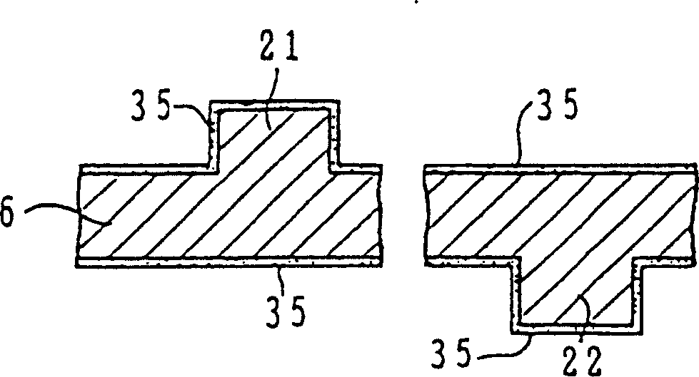
[0048] The second embodiment of the scroll compressor of the present invention is for Figure 4 to illustrate. The scroll compressor structure of the present embodiment and figure 1 and figure 2 The shown scroll compressors are substantially the same, but the structure of the Oldham ring 6 is different. The sectional view of the main part of the Oldham ring 6 constituting the present embodiment is as follows: Figure 4 shown.

[0049] like Figure 4 As shown, on the surface of the Oldham ring 6, a nitriding treatment such as gas nitriding is performed on the steam treatment layer 35 formed in the same manner as in the first embodiment to form a nitriding treatment layer 36.

[0050] With this structure, the surface of the Oldham ring 6 having the steam-treated layer 35 is formed of a different material surface with higher wear resistance by the nitriding-treated layer 36, so that a long life can be obtained as a matter of course.

[0051] In addition...

Example Embodiment

[0054] Example 3

[0055] The third embodiment of the scroll compressor of the present invention is for Figure 5 to illustrate. The structure of the scroll compressor of the present embodiment and figure 1 and figure 2 The shown scroll compressors are substantially the same, but the structure of the Oldham ring 6 is different. The sectional view of the main part of the Oldham ring 6 constituting the present embodiment is as follows: Figure 5 shown.

[0056] like Figure 5 As shown, on the same steam-treated layer 35 as in the first embodiment formed on the surface of the Oldham ring 6, a reformed reforming layer 37 is formed by manganese phosphate reforming treatment.

[0057] With this structure, the surface of the Oldham ring 6 having the vapor treatment layer 35 is formed with a solid lubricating material and a smoothed surface by the modification treatment layer 37 of manganese phosphate. Therefore, since a different material surface with higher sliding propertie...


PUM


Abstract

A scroll compressor having an extended life due to the support structure for the orbiting scroll, even when using a chlorine-free substitution refrigerant. The support structure includes an Oldham ring for supporting an orbiting scroll so as to allow the orbiting scroll more orbiting motion without rotating about a fixing scroll. The Oldham ring is formed of a different material from both a fixing member and the orbiting scroll. Hence, if a boundary lubrication state occurs in mutually sliding parts, only sliding between different materials occurs, and mutual adhesion in the portion of the boundary lubrication state is avoided. As a result, the shortening of the life due to the wearing of the support structure of the orbiting scroll is prevented.

Description

[0001] This case is a divisional application of an invention patent application with the filing date of September 28, 1996, the application number of 96122536.X, and the title of "Scroll Compressor and Its Manufacturing Method" technical field [0002] The present invention mainly relates to a scroll compressor used in commercial and household refrigeration air conditioners and a method for manufacturing the same. Background technique [0003] As an electric compressor for refrigerant air conditioners, there are reciprocating and rotary types of compression parts, and any type is used in the field of refrigeration and air conditioning for household and business use. Now, these two types of compressors are being developed effectively utilizing respective characteristics in terms of cost, performance, and the like. In particular, the scroll compressor has entered practical use by effectively utilizing the characteristics of high efficiency, low noise, and low vibration. [00...

Claims


Application Information

Patent Timeline
IPC IPC(8): F04C29/00F01C17/06F04C18/02F04C29/02
CPCF04C2210/26F05C2203/08F04C2230/92F01C17/066Y10T29/4924F04C2/02
Inventor 河野博之平野秀夫冈秀人
Owner PANASONIC CORP
Why Eureka
Try Eureka