Horizontal grinding type rice milling machine

A rice milling machine, horizontal technology, applied in grain processing, application, grain pod removal, etc., can solve the problems of parts durability, uneven rice milling, and vibration of the rotating shaft, so as to improve the whiteness, improve the The effect of whitening efficiency

Inactive Publication Date: 2004-07-28
SEIREI IND CO LTD +1
View PDF0 Cites 9 Cited by
  • Summary
  • Abstract
  • Description
  • Claims
  • Application Information

AI Technical Summary

Problems solved by technology

[0010] What has become a problem in the existing horizontal grinding type rice milling machine is that in the past, since the spiral groove of the feed roller forms a groove from the start end surface to the end surface of the roller, during rotation, the The pressure of the coarse rice discharged from the outlet end of the outlet to the polishing rice milling chamber is concentrated at one point, and the center of the rotating shaft tends to beat due to the rotation of the pressure concentration point.
Moreover, due to the disposition of the barrier member or the baffle plate on the most entrance side of the polished rice milling chamber facing the end surface of the feed roller, the pressure applied to the polished rice milling chamber in one revolution is different, so that the grinding The rollers vibrate, making rice milling uneven and affecting the durability of parts
[0011] In addition, when assembling the grinding roller or the discharge roller to the rotating shaft, the feed roller is assembled to the rotating shaft while the inlet end side of the rotating shaft cantilevered first, and then the rotating shaft is sequentially passed through each grinding roller. Assembling is performed in the order of sliding the center hole of the center hole to the specified position. However, during the process of assembling the grinding roller on the rotating shaft, the outlet end side is inclined downward due to its weight.
In this way, the assembled grinding roller slides to the outlet end side and comes out, and it also becomes an obstacle when a new grinding roller is assembled to a predetermined position.

Method used


Image

  • Horizontal grinding type rice milling machine
  • Horizontal grinding type rice milling machine
  • Horizontal grinding type rice milling machine

Examples


Embodiment Construction

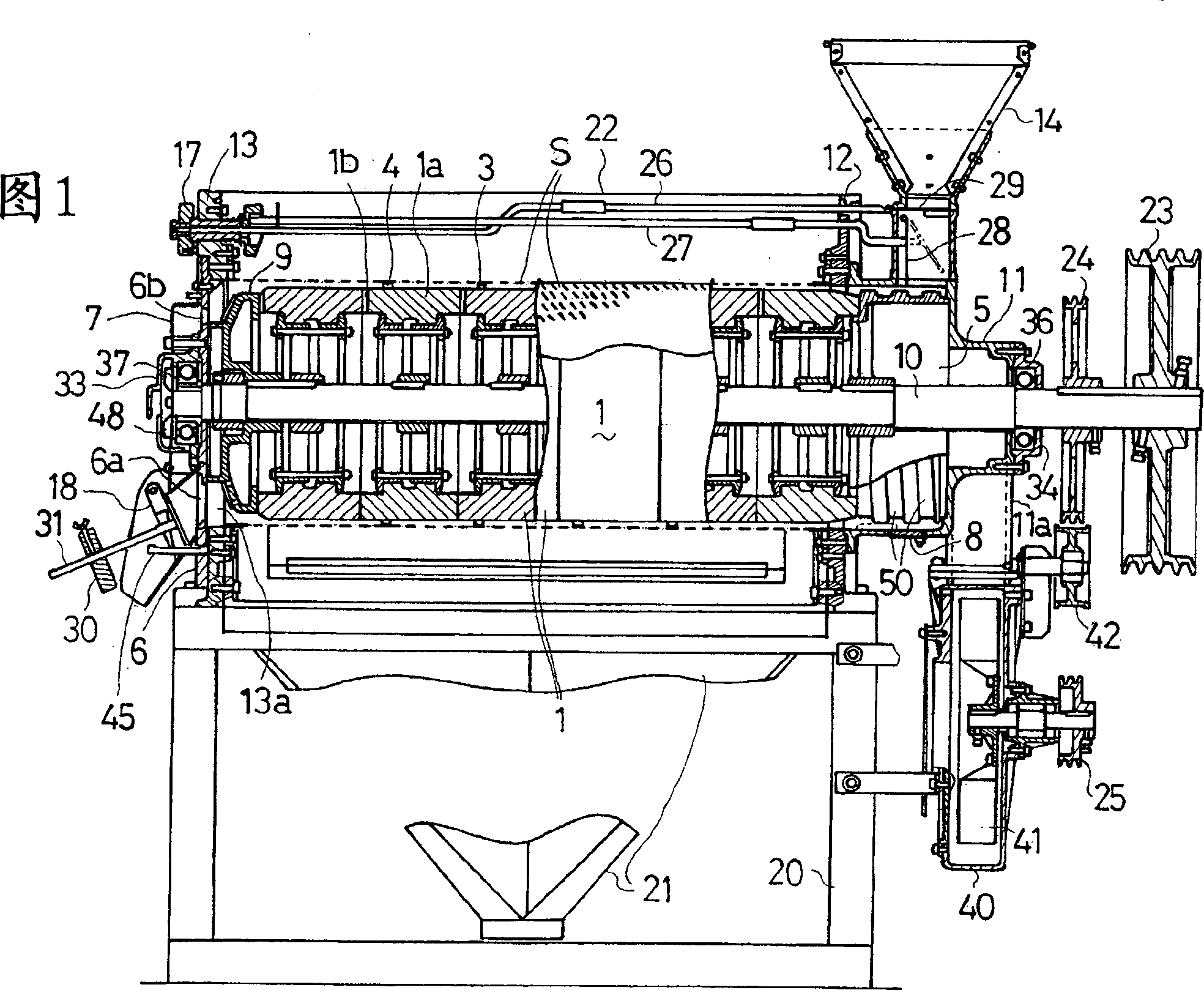
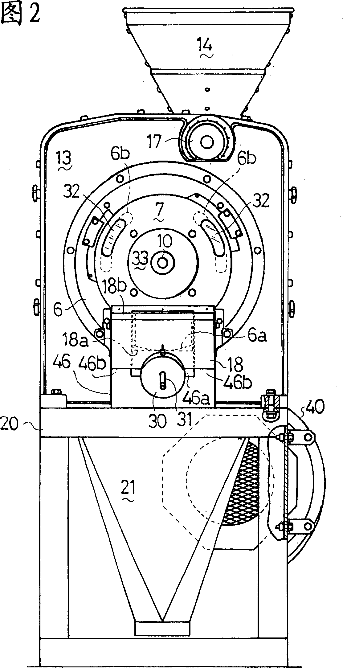
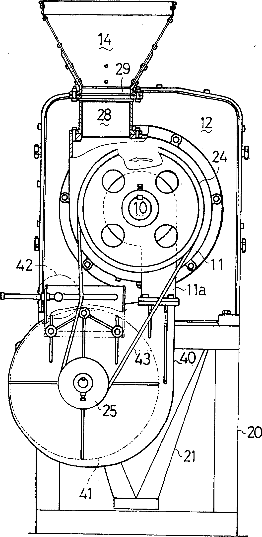
[0053] Below, according to Figure 1~ Figure 4 The overall structure of the horizontal grinding type rice polisher of this invention is demonstrated.

[0054] On the lower supporting frame 20, an inlet-side supporting plate (front plate) 12 and an outlet-side supporting plate (rear plate) 13 are fixedly erected front and rear with a gap between them. A cylindrical rice polishing section cover 22 is provided. In the future, as long as there is no special notice, this machine will use the side of the outlet side support plate 13 (the left side in Figure 1) as the front side, and the side of the inlet side support plate 12 (the right side in Figure 1) as the rear side. illustrate.

[0055] A feed roller casing 11 is fixedly installed on the rear portion of the inlet side support plate 12, and a coarse rice hopper 14 for supplying coarse rice to the polishing rice section is fixedly erected on its upper portion. Inside the coarse rice hopper 14 , an opening and closing gate 29 ...


PUM


Abstract

A horizontal grinding type rice milling machine, comprising a rice milling chamber having grinding rolls fixed around a horizontal rotating shaft and a cylindrical foreign matter removal screen (S) vertically dividable into two screen half parts and covering the grinding rolls concentrically thereto, wherein a plurality of stoppers and flaps formed of arc members curved along the periphery of the circular cross section of the cylindrical screen orthogonal to the axis there of are fixedly installed on the inner peripheral surface of each of the screen half parts obtained by dividing the foreign matter removal screen (S) into two parts so as to be alternately disposed in axial direction, a distance allowing rice to pass while restricting the passing amount of rice is assured between the flaps and the outer periphery of the grinding rolls, and a distance between the stoppers and the outer periphery of the grinding rolls is set so as to not to pass the rice, both screen half parts of the foreign matter removal screen (S) are formed in the same structure and, when the screen half parts are reversed to each other so that both ends thereof in axial direction are replaced with each other.

Description

technical field [0001] The present invention relates to a horizontal grinding type rice milling machine. The structure of the horizontal grinding type rice milling machine is that a feed roller, a grinding roller, and a discharge roller are fixed around a horizontal rotating shaft from one end side to the other end side. , and the grinding roller is covered by a concentric cylindrical bran-removing screen to form a rice polishing chamber, and the coarse rice supplied by the feed roller is polished in the rice polishing chamber, and then discharged from the discharge roller as white rice . Background technique [0002] In the past, feed rollers, (multiple) grinding rollers, and discharge rollers were encircled and fixed from one end side to the other end side of the horizontal rotating shaft, and formed by covering the grinding rollers with concentric cylindrical bran removal screens. There is a known horizontal grinding type rice polishing machine in which the rough rice su...

Claims


Application Information

Patent Timeline
Patent Type & Authority Applications(China)
IPC IPC(8): B02B3/00B02B3/04B02B7/02B02C9/00
CPCB02B3/04B02B3/00B02C9/00B02B7/02
Inventor 大野繁雄
Owner SEIREI IND CO LTD
Why Eureka
Try Eureka