
Optical fiber connection structure

An optical fiber connection and optical fiber technology, which is applied in the structural field of connecting two optical fibers, can solve the problems of dust collection, difficult to cause dust collection effect, etc., and achieve the effect of simple connection

Inactive Publication Date: 2004-08-11
FUJIFILM CORP
View PDF1 Cites 3 Cited by
  • Summary
  • Abstract
  • Description
  • Claims
  • Application Information

AI Technical Summary

Problems solved by technology

In the case of single-mode fiber, it is difficult to cause a dust collection effect because the entire core contacts the fiber for connection by pressing
However, in the case of an optical fiber with a large core diameter such as a multimode optical fiber, it is difficult to make the core end faces come into contact with each other over the entire surface. Therefore, the state where a part of the core end faces are exposed to the outside air is likely to cause a dust collection effect.

Method used


Image

  • Optical fiber connection structure
  • Optical fiber connection structure
  • Optical fiber connection structure

Examples


Embodiment Construction

[0045] Embodiments of the present invention will be described in detail below with reference to the drawings.

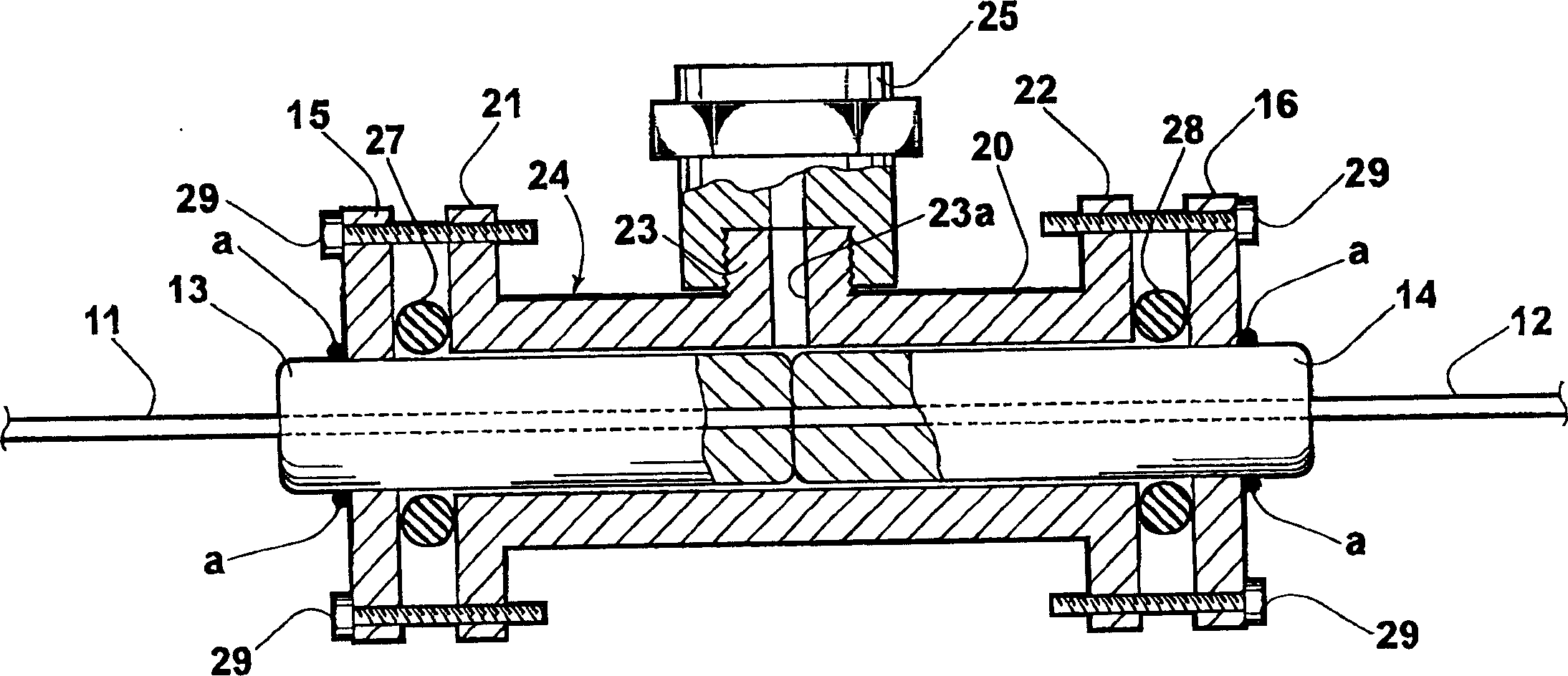
[0046] figure 1 It is a side cross-sectional shape showing the connecting structure of the optical fiber in the first embodiment of the present invention. The connection structure of this optical fiber has two multimode optical fibers (hereinafter referred to as optical fibers) 11,12, each front end of which is inserted and fixed to two cylindrical ferrules 13,14 of the front end; in these ferrules 13,14 Circular flanges 15, 16 fixed near each rear end of each rear end; connector 24 inserted through ferrule 13, 14; O-ring 27 installed on the outer periphery of ferrule 13 inside flange 15; 16 inside and O-ring 28 installed on the outer periphery of ferrule 14.

[0047] The ferrules 13, 14 are formed of ceramics, glass, metal or a combination thereof. In the case of ceramics or glass, it is desirable to metallize the side surface by metal plating or sputtering. Als...


PUM


Abstract

To prevent a dust collection effect from occurring at the tip of an optical fiber brought into contact with each other, and moreover, to make it possible to easily splice the two pieces of optical fibers to each other without the need for a large-scale fusing machine. In an optical fiber splicing structure for splicing two pieces of optical fibers 11, 12 into the state in which each core tip is in contact with the other without being fused, the tip parts of the optical fibers 11, 12 including the core tips are enclosed in a hermetically sealed space such as the internal space of a connector 24 incorporating, for example, ferrules 13, 14, and this hermetically sealed space is filled with an inert gas or a liquid which is transparent to the light propagating in the optical fibers 11, 12 and is not decomposed by the light.

Description

technical field [0001] The present invention relates to a structure for connecting two optical fibers. Background technique [0002] As a structure for connecting two optical fibers, roughly two types of structures are conventionally known. One is a structure in which the ends of two optical fibers are fused in a state where the cores are coaxially aligned. The other is a structure in which two optical fibers are connected without fusion splicing, but in a state where the ends of the cores are in contact with each other. The more specific structure of the latter is as described in Patent Document 1. A well-known connector consists of two ferrules that respectively fix the front ends of two optical fibers, and when the core front ends of each optical fiber are matched, A common ferrule through which these ferrules are inserted, and a member (mechanism) that holds these ferrules in a state where the core tips of two optical fibers are in contact with each other are constitut...

Claims


Application Information

Patent Timeline
Patent Type & Authority Applications(China)
IPC IPC(8): G02B6/38
CPCG02B6/3849G02B6/387G02B6/4238
Inventor 寺村友一冈崎洋二山中英生
Owner FUJIFILM CORP
Learn More