Antenna unit

An antenna unit, radiating antenna technology, applied in the directions of antennas, resonant antennas, antenna parts, etc., can solve problems such as unsuitable antennas, and achieve the effect of reducing production costs

Inactive Publication Date: 2004-08-11
L K PROD OY
View PDF1 Cites 23 Cited by
  • Summary
  • Abstract
  • Description
  • Claims
  • Application Information

AI Technical Summary

Problems solved by technology

[0005] The disadvantage of the unit shown in Figure 1 is that its components must have a certain electrical size, which limits the design of the unit
Also, the characteristics of the antenna using this unit may not be suitable for flat and thin radio equipment

Method used


Image

  • Antenna unit
  • Antenna unit
  • Antenna unit

Examples


Embodiment Construction

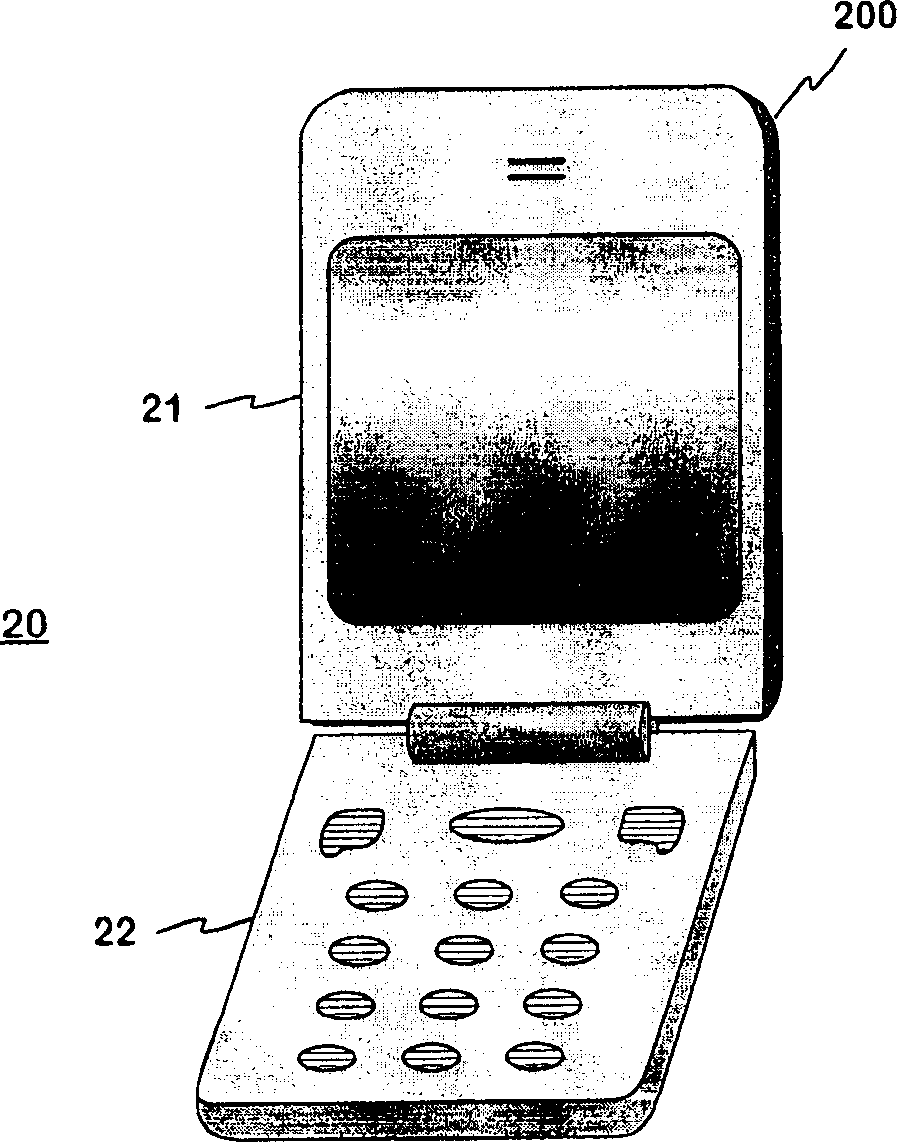
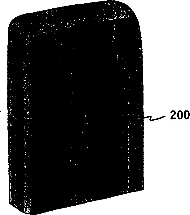
[0022] Figure 2a with 2b An example of a radiating antenna unit according to the present invention is shown. The antenna unit 200 belongs to Figure 2a A radio device is shown, which in this example is a collapsible communication device 20 . The communication device has a first part 21 and a second part 22 which are pivotable relative to each other about a hinge situated between them. Figure 2b Only the antenna unit 200 is shown. This is the single conductive piece that forms the rear and narrower sides and upper end face of the first part 21 . It can be produced, for example, from aluminum by extrusion. The size of the antenna element is not limited to the wavelength corresponding to the operating frequency. The elements are large compared to a quarter wavelength, so that good radiation and reception characteristics can be obtained. Radiator placement on the outer surface of the radio has the same effect. In the final product, the antenna unit 200 as well as the anten...


PUM


Abstract

A radiating antenna element intended to be used in small-sized radio devices, and a radio device having an antenna element according to the invention. The antenna element is part of the covers of a radio device. The antenna element may be conductive throughout, or it may comprise a dielectric portion and a conductive portion, which constitute a single integral component. The radiating portion of the antenna element is relatively large, e.g. in a foldable phone (20) the antenna element (200) may comprise the whole cover of a foldable part (21) except for the front side. The radiating element is advantageously fed electromagnetically through a feed element. As the radiating element is relatively large and is located on the outer surface of the device, the radiation characteristics of the antenna are good, and the space required by the antenna inside the device is relatively small.

Description

technical field [0001] The invention relates in particular to a radiating antenna unit intended for small radio equipment. The invention also relates to a radio device having an antenna unit according to the invention. Background technique [0002] In antenna design, available space is an important factor. It is fairly easy to make a good quality antenna if there are no size constraints. In small radio devices, such as mobile phones, for convenience, attempts are made to avoid antennas protruding outside the housing of the device. This means that as devices get smaller, less space is available for antennas, making antenna design even more challenging. [0003] Internal antennas in mobile terminals usually have a planar structure: the antenna includes a radiation plane and a ground plane parallel to it. The electrical properties of planar antennas, such as bandwidth and antenna gain, depend inter alia on the distance between the planes. As the mobile terminal becomes sma...

Claims


Application Information

Patent Timeline
Patent Type & Authority Applications(China)
IPC IPC(8): H01Q1/24H01Q1/38H01Q5/00H01Q5/371H01Q9/04H01Q19/00
CPCH01Q1/243H01Q9/0421H01Q5/371H01Q5/0058H01Q9/0457H01Q1/38H01Q9/0442H01Q19/005H01Q9/0414
Inventor J·米科拉P·安纳马亚E·卡里斯塔杰
Owner L K PROD OY
Why Eureka
Try Eureka