Brushless DC electric motor

A technology of DC motors and circuit boards, applied in the direction of generators/motors, electric components, machines/engines, etc.

Inactive Publication Date: 2004-08-11
ADVANCED ROTARY SYST
View PDF2 Cites 25 Cited by
  • Summary
  • Abstract
  • Description
  • Claims
  • Application Information

AI Technical Summary

Problems solved by technology

This known device is not easy to manufacture, the greatest difficulty is to manufacture the disc rotor with variable polarity electromagnetic poles

Method used


Image

  • Brushless DC electric motor
  • Brushless DC electric motor
  • Brushless DC electric motor

Examples


Embodiment Construction

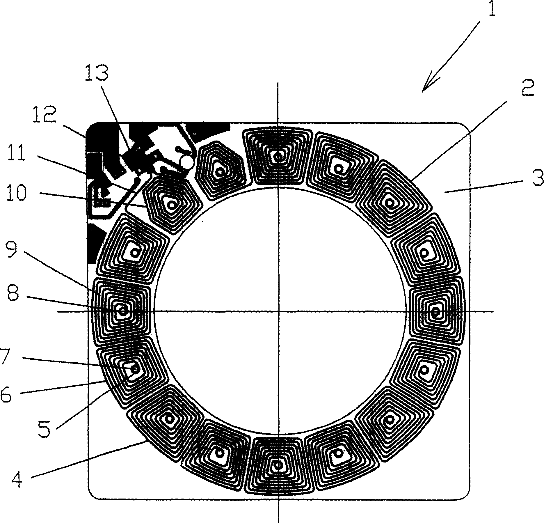
[0017] Described below is a new type of brushless DC motor using a stator coil of a printed circuit board. In our description below we will refer to this printed circuit board as a stator board or a circuit board. Magnetic rotors are made of permanent magnetic material and may be part of a single unit or a series of units with identical poles. This whole or unit will be referred to hereinafter as the rotor disk or the rotor / impeller. The simple instructions below are divided into six sections: Stator Plate, Rotor, Motor Description, Combined Motor / Blower, Motor Controller, and Operating Instructions.

[0018] Stator plate

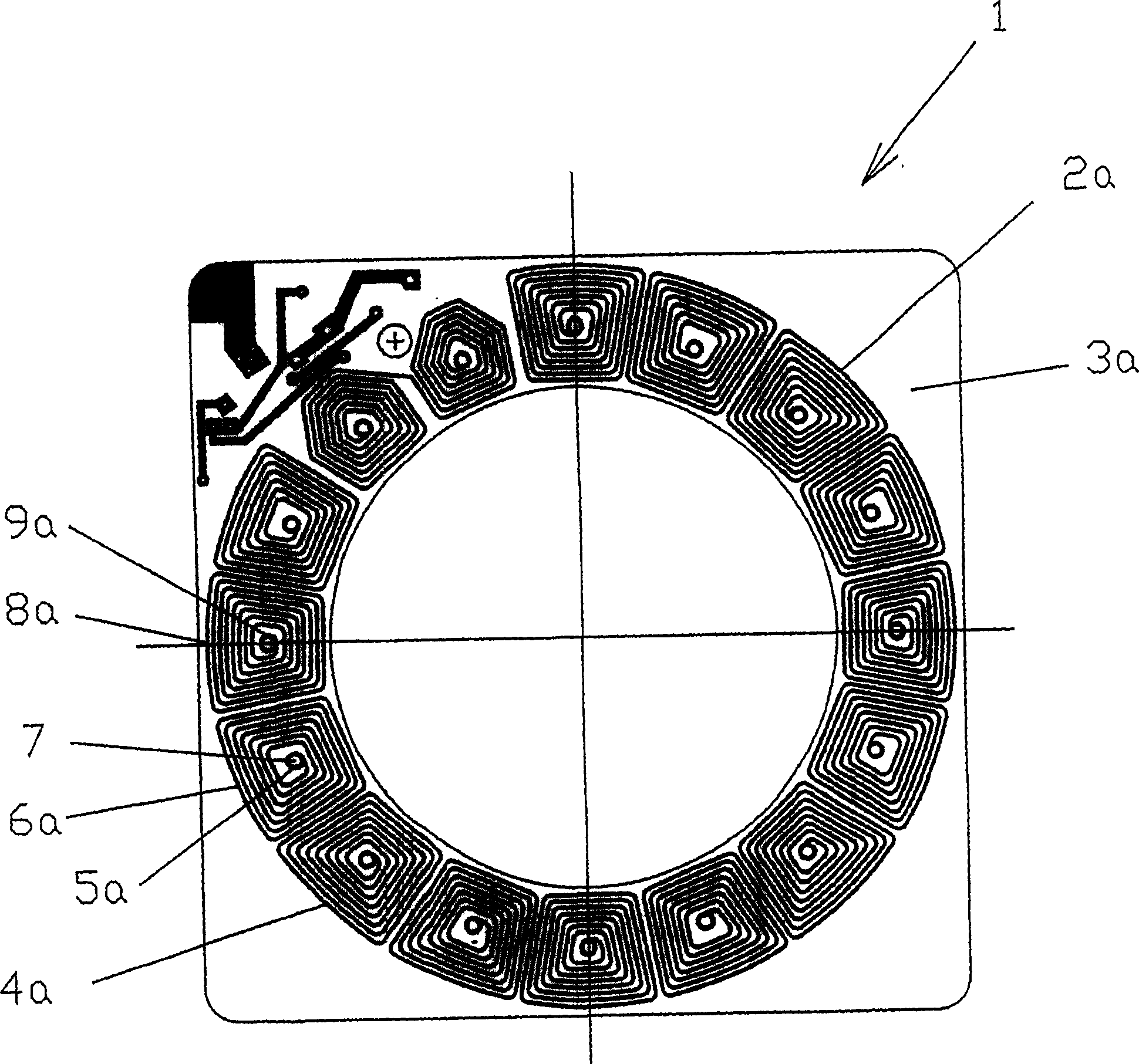
[0019] The stator plate described here is designed for use with an H-bridge controller. Figure 1A It is the front side of the stator plate 1, including the coil 2 located on the circumference of the stator plate on the circuit board substrate 3, which is etched from metal, usually copper. Figure 1B is the rear side (perspective) of the stator plate 1, ...


PUM


Abstract

An electric motor comprises a housing, a magnetic rotor and a stator which comprises at least one circuit board. The magnetic rotor comprises a disk with circumferentially arrayed magnetic poles. The circuit board on each side comprises one layer of circumferentially arrayed coil windings arranged in pairs, thus each pair made as a spiral that extends from a center of a start coil winding to a center of an end coil winding with the same turn direction of the spiral in relation to each of centers. The layers are the same in transparent view and shifted angularly in such a way thus centers of the start coil windings from one side of the circuit board coincided and electrically connected by via's with centers of the end coil windings on the other side of the circuit board.

Description

[0001] related application [0002] This application is a continuation-in-part of US Provisional Patent Application SN.60 / 301,229, issued June 26,2001. technical field [0003] This invention is related to electrical engineering, especially electromagnetic machinery, and can be used in the production of electronic equipment for various purposes, such as: ventilation equipment, compressors, pumps, steering wheels for electric vehicles, etc. Background technique [0004] The mechanics of the rotor-stator interaction mode on the end face are well known, in this mode the rotor is a disk with alternating magnetic permanent magnets on the bottom surface located on the circumference; the stator is made in the shape of a disk (ring) coaxial with the rotor Mounting, the electromagnetic stator coils are mounted on the end face of the stator. For example, US Patent No. 5440185, IPC 6 H02K 21 / 12 describes a DC brushless motor (electric) belonging to this type of machinery. Known devic...

Claims


Application Information

Patent Timeline
Patent Type & Authority Applications(China)
IPC IPC(8): H02K1/27H02K3/26H02K7/14H02K21/24H02K29/00
CPCH02K3/26H02K2211/03Y10S310/06H02K21/24H02K7/14H02K1/2793F04D25/0653H02K1/2795
Inventor 爱德华·洛帕京斯基丹尼尔·谢弗沙韦伊·罗森菲尔德列夫·费多谢耶夫
Owner ADVANCED ROTARY SYST
Why Eureka
Try Eureka