Real time measuring method for load rotor inertia
A real-time measurement, rotor inertia technology, applied in measurement devices, machine/structural component testing, static/dynamic balance testing, etc., can solve problems such as lack of elasticity, difficulty in use, and lack of intelligent products.
Inactive Publication Date: 2004-09-01
DELTA ELECTRONICS INC
View PDF0 Cites 1 Cited by
- Summary
- Abstract
- Description
- Claims
- Application Information
AI Technical Summary
Problems solved by technology
Some drives are designed to use the load rotor inertia as a parameter to be input into the drive by the user. This method lacks flexibility, and if the user does not know the meaning of the load rotor inertia, the product will lack the advantages of intelligence and use difficulties.
Method used
View moreImage
Smart ImageViewing Examples
Examples
no. 1 example
[0100] J=9e-5, G=1, Jm=2J, JL=J, the measurement result W1+W20.8. Its time response graph is as Figure 7 shown.
no. 2 example
[0102] J=9e-5, G=1, Jm=2J, JL=10J, the measurement result W1+W24.5. Its time response graph is as Figure 8 shown.
no. 3 example
[0104] J=9e-5, G=10, Jm=2J, JL=J, the measurement result W1+W20.9. Its time response graph is as Figure 9 shown.
Login to View More PUM
 Abstract
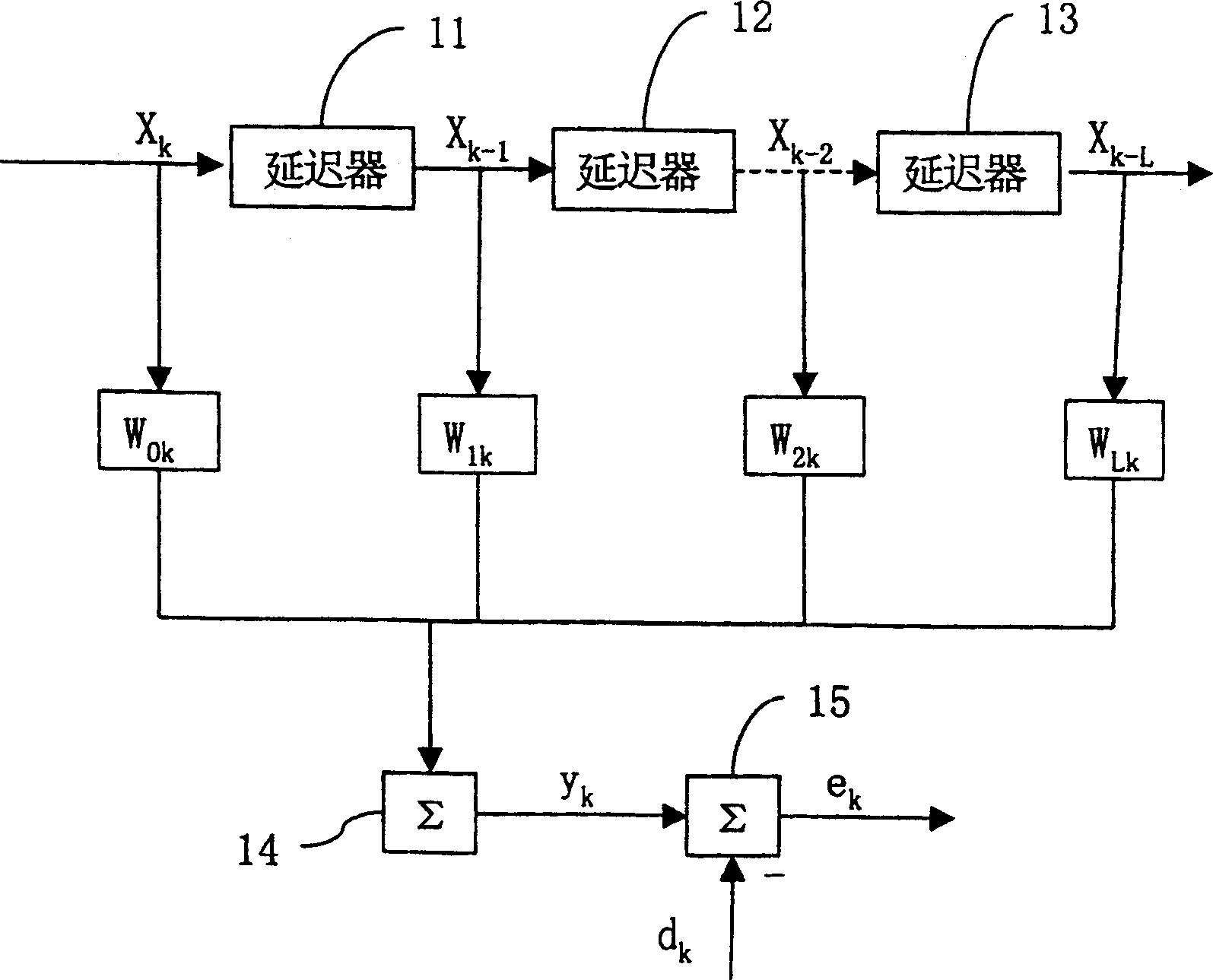
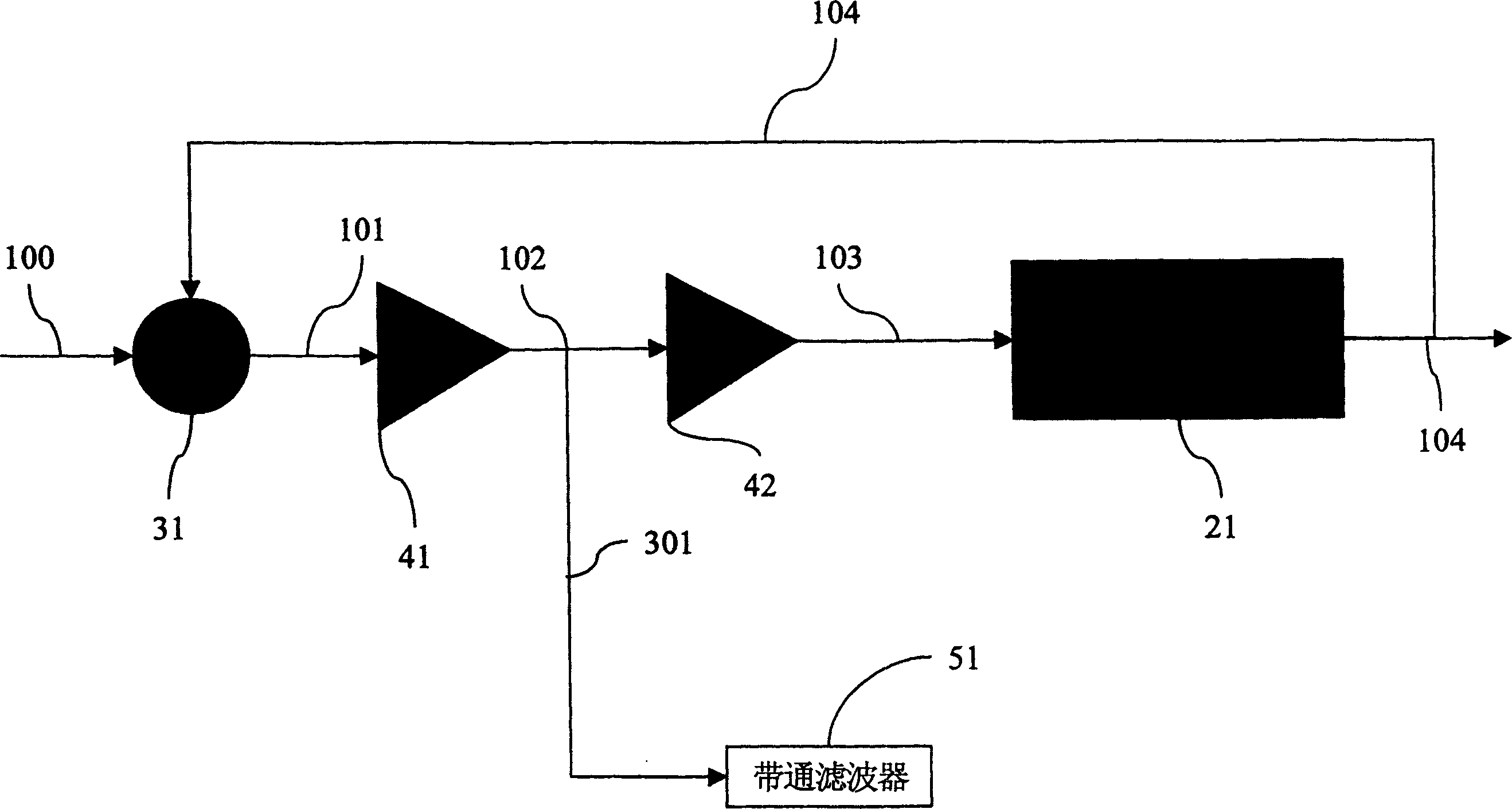
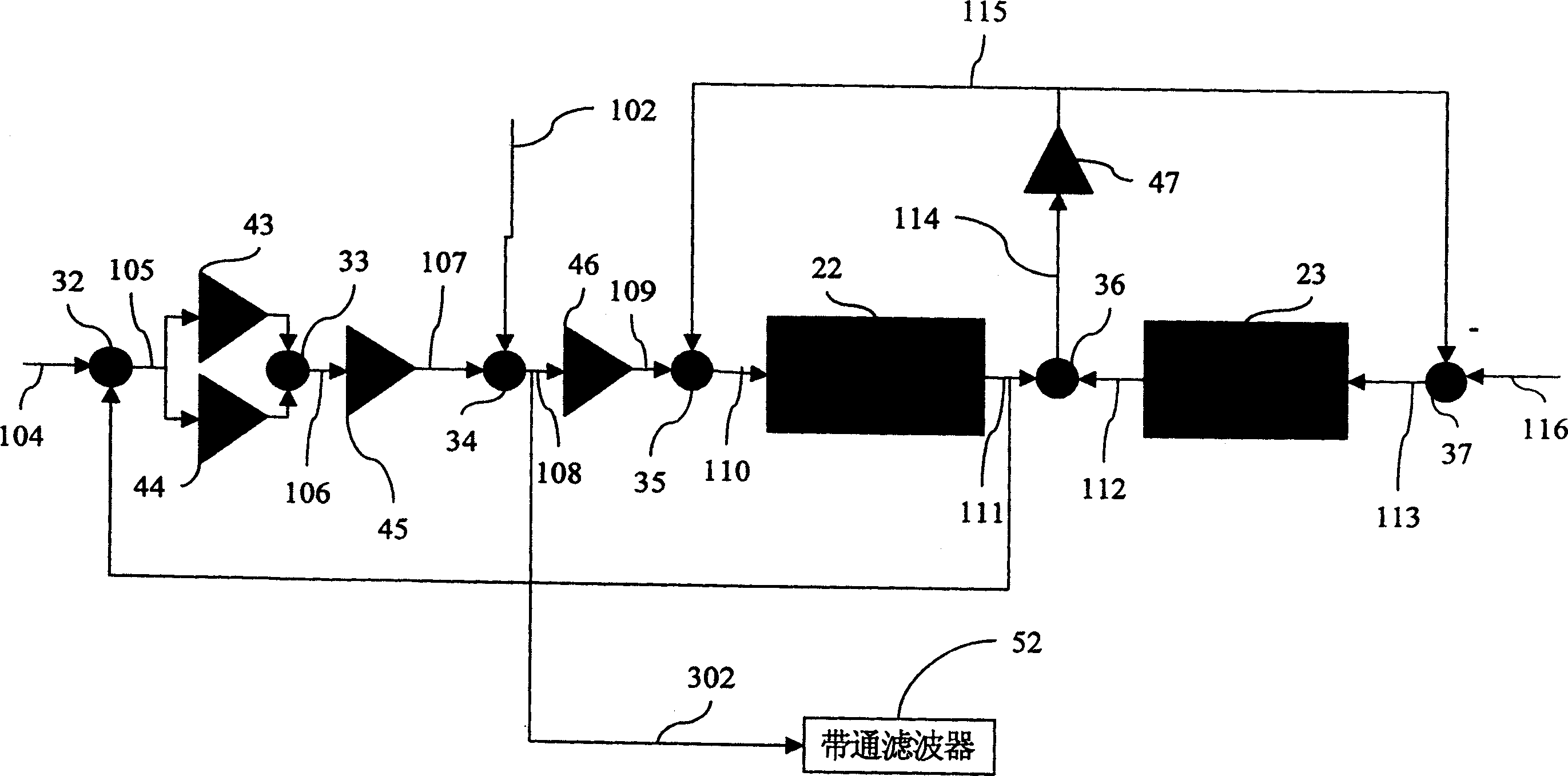
The invention reveals a real-time load rotor moment of inertia measuring method, by the adaptive filter and the minimum square method, real-timely measuring the moment of inertia of load rotor, using a moment- of-inertia known model electric machine, using the current signal of the model electric machine as one of the input signals of the adaptive filter, and using the error quantity obtained by subtracting the current signals of driving electric machine and model electric machine from each other as the other signal of the adaptive filter, then by the algorithm of the adaptive filter cooperating with the minimum square, operating the two input signal, able to measure load moment of inertial of load at once.
Description
technical field [0001] The invention relates to a method for measuring the moment of inertia, in particular to a method for real-time measuring the inertia of the load rotor of an AC servo driver. Background technique [0002] The basic structure of the AC permanent magnet synchronous motor is similar to that of the traditional synchronous motor. There are three-phase windings on the stator side, while the excitation part on the rotor side is generated by permanent magnets, without excitation circuits, slip rings, and brushes. It has high power-to-volume ratio, high Due to the advantages of efficiency and low torque ripple, it is suitable for driving devices of precision servo mechanisms, such as high-precision or high-response processing machinery platforms. [0003] In the currently widely used servo control system, when designing an AC brushless servo drive, the moment of inertia of the load is an important parameter for designing the server. This parameter must be accura...
Claims
Login to View More Application Information
Patent Timeline
 IPC IPC(8): G01M1/10
Inventor 蔡清雄陈博铭
Owner DELTA ELECTRONICS INC
- R&D Engineer
- R&D Manager
- IP Professional
- Industry Leading Data Capabilities
- Powerful AI technology
- Patent DNA Extraction
Learn More Browse by: Latest US Patents, China's latest patents, Technical Efficacy Thesaurus, Application Domain, Technology Topic, Popular Technical Reports.
© 2024 PatSnap. All rights reserved.Legal|Privacy policy|Modern Slavery Act Transparency Statement|Sitemap|About US| Contact US: help@patsnap.com


