
Apparatus, method, and control method for driving led with ac power

A light-emitting diode and power-driven technology, which is applied to the device and control field of driving light-emitting diodes with alternating current power, can solve the problems of shortening the life of organic light-emitting diodes and the like

Active Publication Date: 2004-09-01
AU OPTRONICS CORP
View PDF0 Cites 6 Cited by
  • Summary
  • Abstract
  • Description
  • Claims
  • Application Information

AI Technical Summary

Problems solved by technology

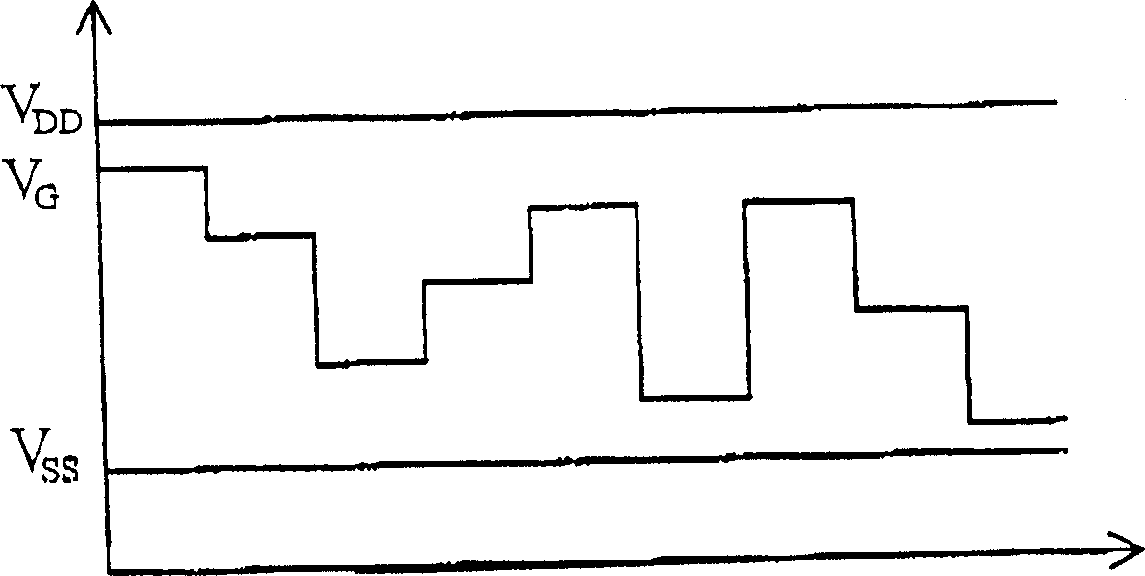
[0005] Please refer to figure 1 , in a typical OLED display driving method, the system power supply V DD , always above V SS , the reason is that a typical organic light-emitting diode can only light up in this state; in addition, the gate voltage V of the thin film transistor G always between V DD with V SS In between, in this state, the thin film transistor will gradually accumulate charge, and at the same time, the lifetime of the organic light emitting diode will gradually shorten, so this method is not ideal for displays using active matrix organic light emitting diodes Way

Method used


Image

  • Apparatus, method, and control method for driving led with ac power
  • Apparatus, method, and control method for driving led with ac power
  • Apparatus, method, and control method for driving led with ac power

Examples


Embodiment Construction

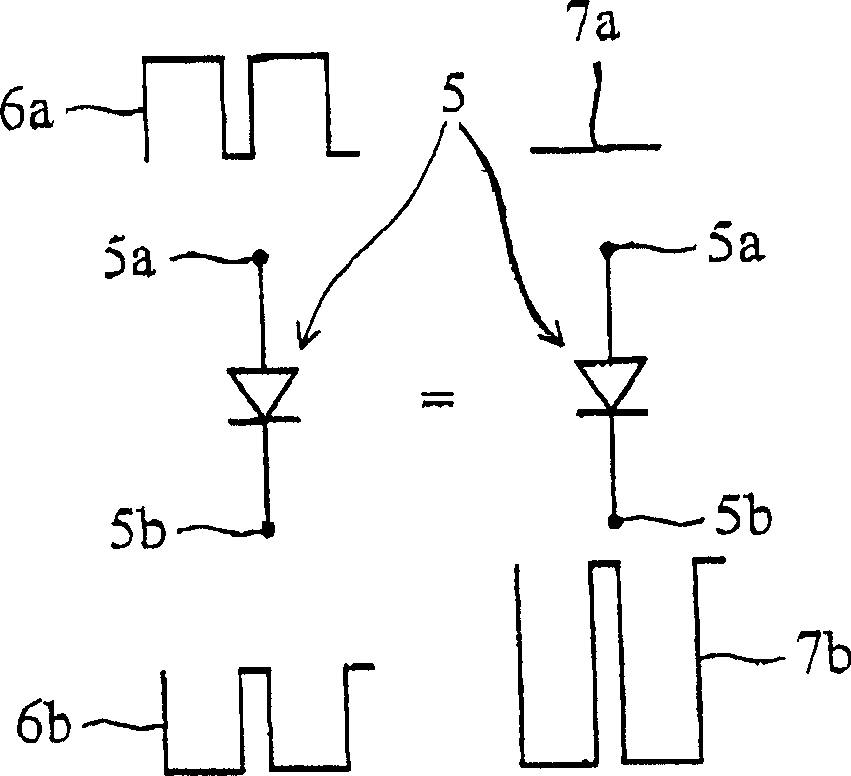
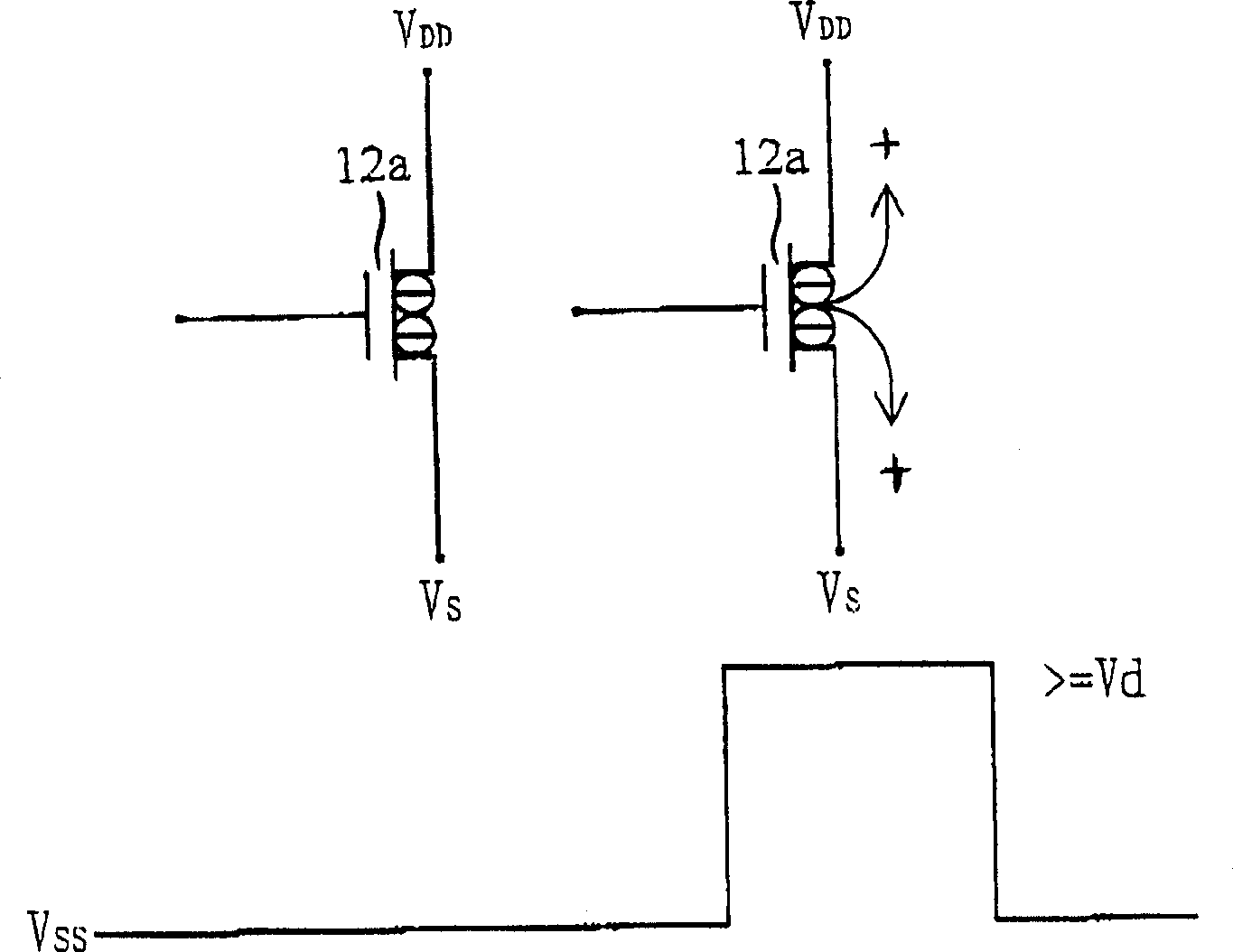
[0013] now please refer to Figure 2A and Figure 2B , diode 5 (such as: organic light-emitting diode or other organic light-emitting components) will have appropriate voltage conversion to carry out the reverse bias familiar to those skilled in the art (the anode 5a applies the voltage shown in 6a, and the cathode 5b applies the voltage shown in 6b or the anode 5a applies a voltage as shown in 7a, and the cathode 5b applies a voltage as shown in 7b), to prevent the degradation of the organic light emitting diode and the active matrix organic light emitting diode component, the reverse bias operation can be in a related on the gate 12a of the thin film transistor, as Figure 2B shown (as is well known to those skilled in the art).

[0014] now please refer to image 3 , the system 1 for providing an active matrix organic light emitting diode display includes a control circuit 20, a power controller 30 connected to the control circuit 20 when operating, and an active matrix ...


PUM


Abstract

The invention is a device and method for supplying alternate current power to active matrix organic brightening diode. The polarity and voltage supplied for active component such as film transistor in order to drive the active matrix organic brightening diode can be changed into reverse one or the voltage value is changed in a special period; in the next period, the changed power will be changed into the original state.

Description

technical field [0001] The invention relates to a circuit and method for driving an organic light-emitting diode with alternating voltage or current. Background technique [0002] Many displays for presenting information are based on light emitting diodes, which include organic light emitting diodes and active matrix light emitting diodes. [0003] Generally speaking, the driving voltage of the OLED will increase with the working time, and the brightness of the OLED will decrease accordingly. In addition, the change of the terminal voltage connecting the OLED to the thin film driving transistor will also affect the brightness of the thin film transistor. Work. [0004] Once the voltage of the thin film transistor (such as the drain or source voltage) changes, the driving current of the thin film transistor under the same grayscale data input will decay, which will gradually reduce the brightness of the display. [0005] Please refer to figure 1 , in a typical OLED display...

Claims


Application Information

Patent Timeline
Patent Type & Authority Applications(China)
IPC IPC(8): H01L51/50G09G3/00G09G3/20G09G3/32G09G5/00H05B33/08H05B33/14
CPCG09G3/3208G09G2320/0204G09G2330/02G09G2310/0245G09G2310/0254G09G2310/0256
Inventor 胡硕修施立伟林巧茹陈文焜
Owner AU OPTRONICS CORP
Learn More