
Noise cancellor

A technology of noise eliminator and impulse noise, applied in instruments, electrical components, voice analysis, etc., can solve problems such as received signal distortion

Inactive Publication Date: 2004-09-08
GK BRIDGE 1
View PDF2 Cites 7 Cited by
  • Summary
  • Abstract
  • Description
  • Claims
  • Application Information

AI Technical Summary

Problems solved by technology

However, there is no difference between this method and the method shown in Figs. 6A-6D, because the impulse noise is eliminated by keeping the signal level at the signal level immediately before the impulse noise occurs, thereby causing distortion of the received signal

Method used


Image

  • Noise cancellor
  • Noise cancellor
  • Noise cancellor

Examples


Embodiment Construction

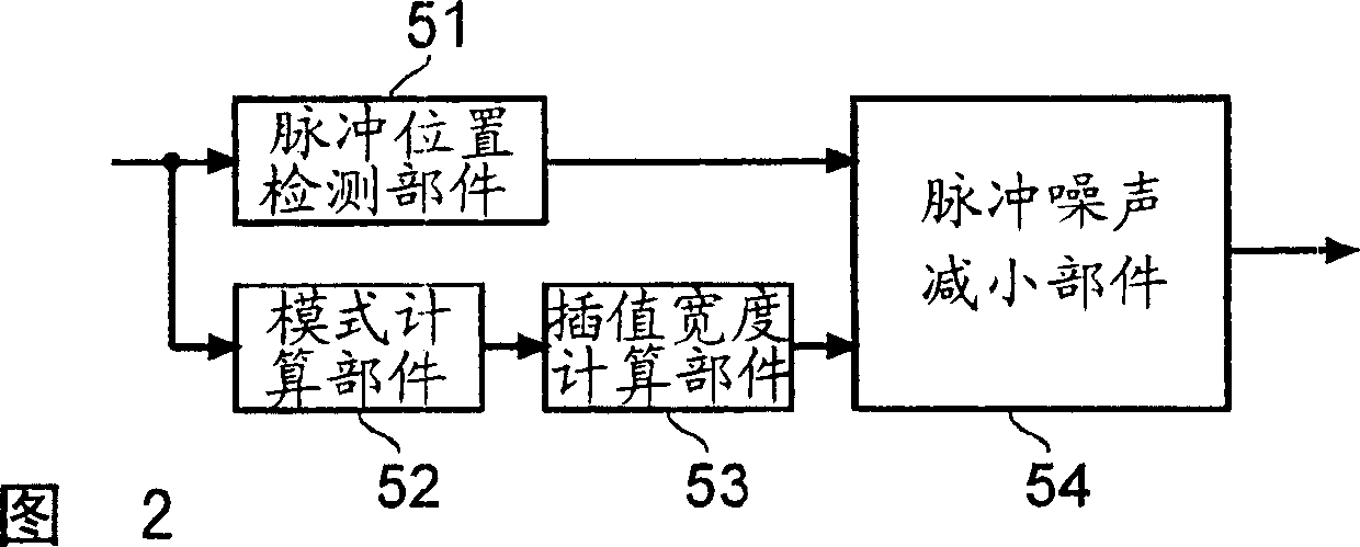
[0016] An embodiment of the present invention will be described below with reference to the accompanying drawings. FIG. 1 is a block diagram showing the internal configuration of an FM receiver including a noise canceller according to the present invention, and FIG. 2 is a block diagram showing the internal configuration of the noise canceller according to the present invention.

[0017] FM receiver device shown in Fig. 1 comprises: antenna 1, is used for receiving broadcast signal; (radio frequency) amplification; intermediate frequency amplification part (IF) 3, is used for converting the FM reception signal that FE2 selects into the intermediate frequency of 10.7MHz, and amplifies; Detection part 4, is used for by detecting the FM reception signal that carries out frequency conversion through IF3 to come Extract modulation signal; Noise eliminator (NC) 5, is used for eliminating the noise superimposed on the modulation signal obtained by detection part 4 detection; The sig...


PUM


Abstract

If a mode calculating section ( 52 ) judges that an inputted modulated signal is nearly in a no-sound state, the interpolation width determined by an interpolation width calculating section ( 53 ) is increased, whereas if the mode calculating section ( 52 ) judges that the inputted modulated signal contains a lot of high-frequency components, the interpolation width determined by the interpolation width calculating section ( 53 ) is decreased.

Description

technical field [0001] The present invention relates to a noise canceller for canceling noise contained in an input signal, and more particularly, to a noise canceller included in an FM (Frequency Modulation) receiver device for canceling noise contained in an FM reception signal. Background technique [0002] In a vehicle-mounted FM receiving apparatus, a received FM signal has impulse noise such as ignition noise superimposed thereon, and therefore, in order to eliminate such impulse noise contained in an FM reception signal, a noise canceller is provided. [0003] With a conventional noise canceller, when receiving a composite signal having impulse noise superimposed thereon as shown in FIG. 6A, the impulse noise is detected by passing the composite signal through an HPF (High Pass Filter). When the HPF detects impulse noise, an impulse noise detection signal as shown in FIG. 6B is generated. When the impulse noise detection signal is applied to an integrator, the integr...

Claims


Application Information

Patent Timeline
Patent Type & Authority Applications(China)
IPC IPC(8): G10L21/0208H04B1/10
CPCG10L19/005G10L21/0208H04B1/1027H04B1/10
Inventor 平正明
Owner GK BRIDGE 1
Learn More