

Incorporation of mathematical constraints in methods for dose reduction and image enhancement in tomography
a tomography and dose reduction technology, applied in image generation, image enhancement, instruments, etc., can solve the problems of reducing resolution, missing projection data, and projections that can be acquired in the typical, so as to reduce the number of projections or fluxes, the effect of increasing scan speed
- Summary
- Abstract
- Description
- Claims
- Application Information
AI Technical Summary
Benefits of technology
Problems solved by technology
Method used
Image

Examples
example 1
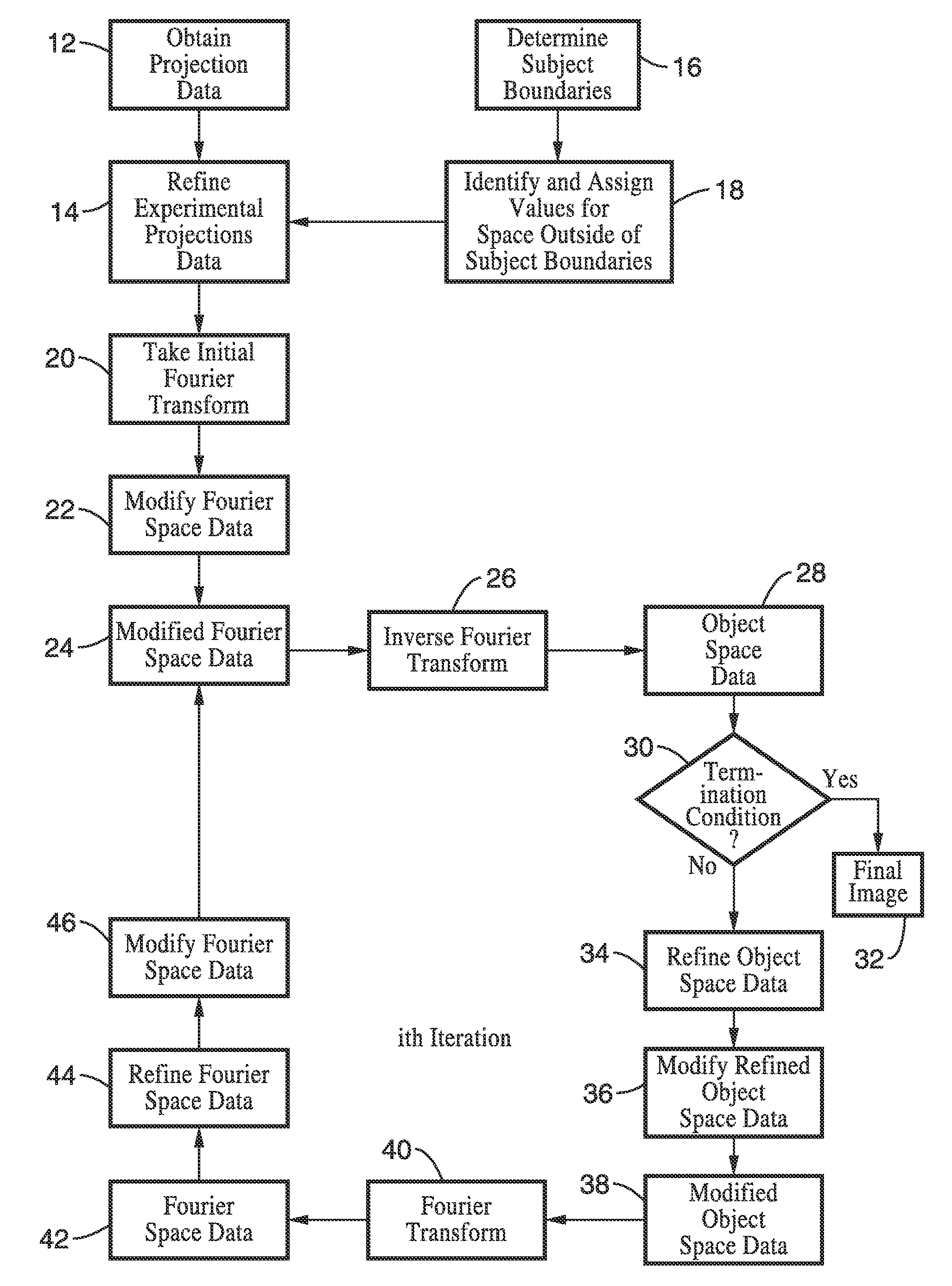
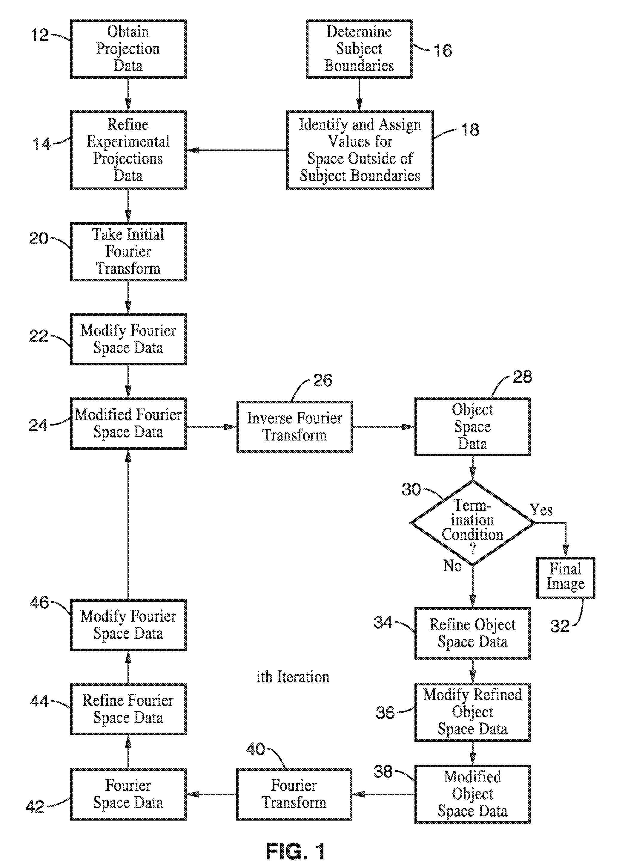
[0081]In order to demonstrate the functionality of the invention and the general principles behind the refining sub-transformations, comparative reconstructions of a phantom were conducted. In the embodiments tested, the object space was placed on a Cartesian grid, and the Fourier space was on a pseudopolar grid that was oversampled by a factor of 2 with respect to the object space grid. A Fourier transform of the acquired projections at a plurality of angles and slice locations was performed by a fractional fast Fourier transform with parameters such that when the transformed projections were placed onto a grid in Fourier space the Fourier slices were placed on the closest pseudopolar grid precisely. However, in this example the initializing modification of Fourier space was not performed.
[0082]The inverse transformation of said Fourier space data to provide object space data was performed by an Inverse Pseudopolar Fast Fourier Transform (PPFFT−1) and forward Fourier transformation...
example 2
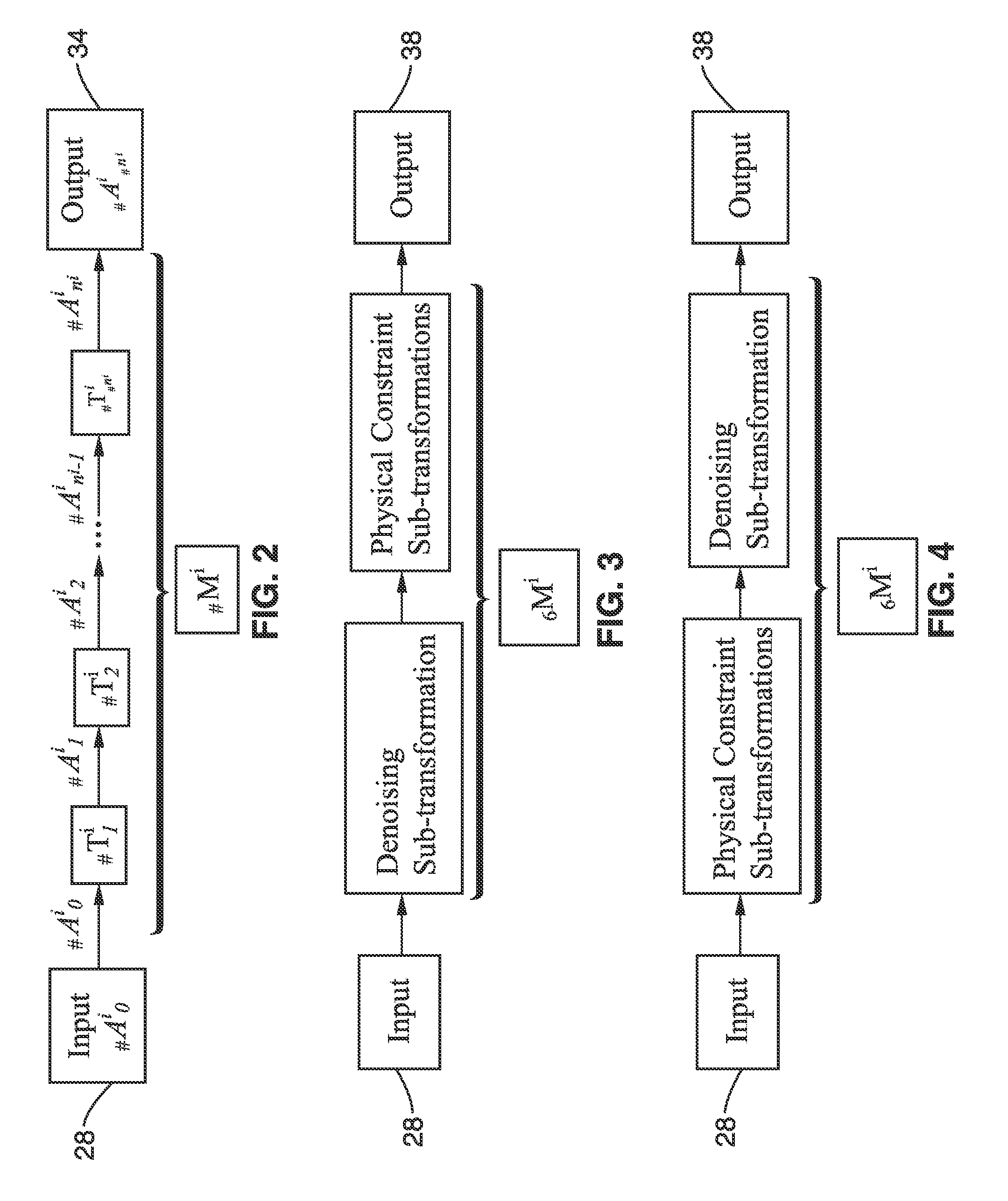
[0086]In FIG. 6A through FIG. 6D, the noise is simulated in the projections and the tomographic reconstructions are performed on a mouse phantom. FIG. 6B shows the conventional reconstruction at full dose defined by 180 projections and 12000 photon flux. For comparison, FIG. 6C demonstrates the embodiment shown in FIG. 4 using the adaptive Wiener filtering (applied in each iteration) with 90 projections and 6000 photons, i.e. 75% less dose. FIG. 6D demonstrates the results from the configuration shown in FIG. 3 as previously discussed with 90 projections and 6000 photons, i.e. 75% less dose than required in the art.
[0087]To quantify the image quality, the signal to noise ratio (SNR) was calculated for different tissues. For the conventional at full dose (FIG. 6B), the SNR is calculated to be: Bone: 13.2646 Heart: 9.349 Soft Tissue: 8.7087 Lung & Skin: 8.3156 VF: 4.8091 Air: −0.22644; for preferred embodiment 2 (FIG. 6C), the SNR is calculated to be: Bone: 17.7948 Heart: 17.7376 Soft...
example 3
[0089]One of the primary purposes of the invention of dose reduction in medical imaging that can be achieved by reducing either the photon fluence and or number of projections and using the methods is shown in FIG. 7A through FIG. 7F. The methods of this invention are experimentally demonstrated in FIG. 7 with comparative reconstructions of an image quality phantom using synchrotron x-ray irradiation. Tomographic projections were acquired at 200 equal angle intervals. The images to the left represent the conventional reconstruction and the images to right represent reconstruction via preferred embodiment 1, with experimental projections mapped onto nearest pseudopolar line as described above. The results demonstrate that the methods described here have driven the reconstruction to a less noisy state consistent with the actual phantom and experimental projections. FIGS. 7C and 7D demonstrate that the contrast is significantly improved with the use of the methods. The improvement is q...
PUM
 Abstract
Description
Claims
Application Information