
Mixed motor vehicles

A hybrid electric vehicle and electric motor technology, which is applied to improve the driving performance of hybrid electric vehicles, hybrid electric vehicles, and the field of realizing hybrid electric vehicles, which can solve problems such as transmissions that have not yet been used

Inactive Publication Date: 2004-09-22
HINO MOTORS LTD
View PDF1 Cites 7 Cited by
  • Summary
  • Abstract
  • Description
  • Claims
  • Application Information

AI Technical Summary

Problems solved by technology

Thus, it can be said that transmissions including hydraulic torque converters have not been used in hybrid vehicles

Method used


Image

  • Mixed motor vehicles
  • Mixed motor vehicles

Examples


Embodiment Construction

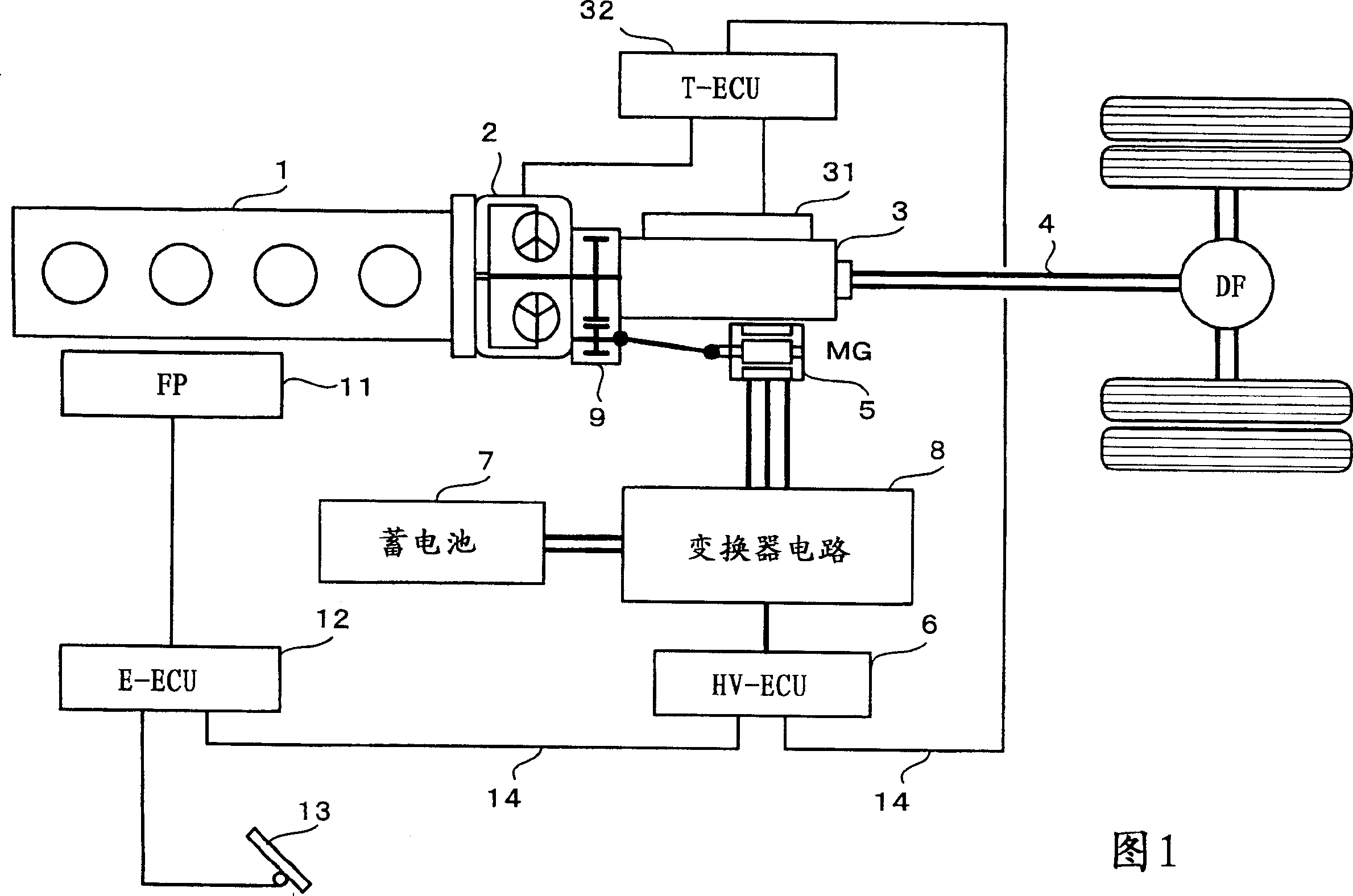
[0020] FIG. 1 is a block diagram showing the structure of a hybrid vehicle according to an embodiment of the present invention. The output shaft of the internal combustion engine 1 is directly connected to the input shaft of the hydraulic torque converter 2 . The output shaft of the hydraulic torque converter 2 is fixedly connected to the input shaft of the multi-stage transmission 3 via a coupling unit 9 . The multi-stage transmission 3 includes an actuator 31 for mechanically controlling the shift-combination of the multi-stage transmission 3, and a transmission control circuit 32 for electrically controlling the actuator. The transmission control circuit 32 includes an program control circuit (ECU).

[0021] The transmission control circuit 32 determines the optimal gear ratio of the multi-stage transmission according to input information including vehicle speed, engine speed, accelerator pedal operation information and the like. The actuator 31 mechanically controls the ...


PUM


Abstract

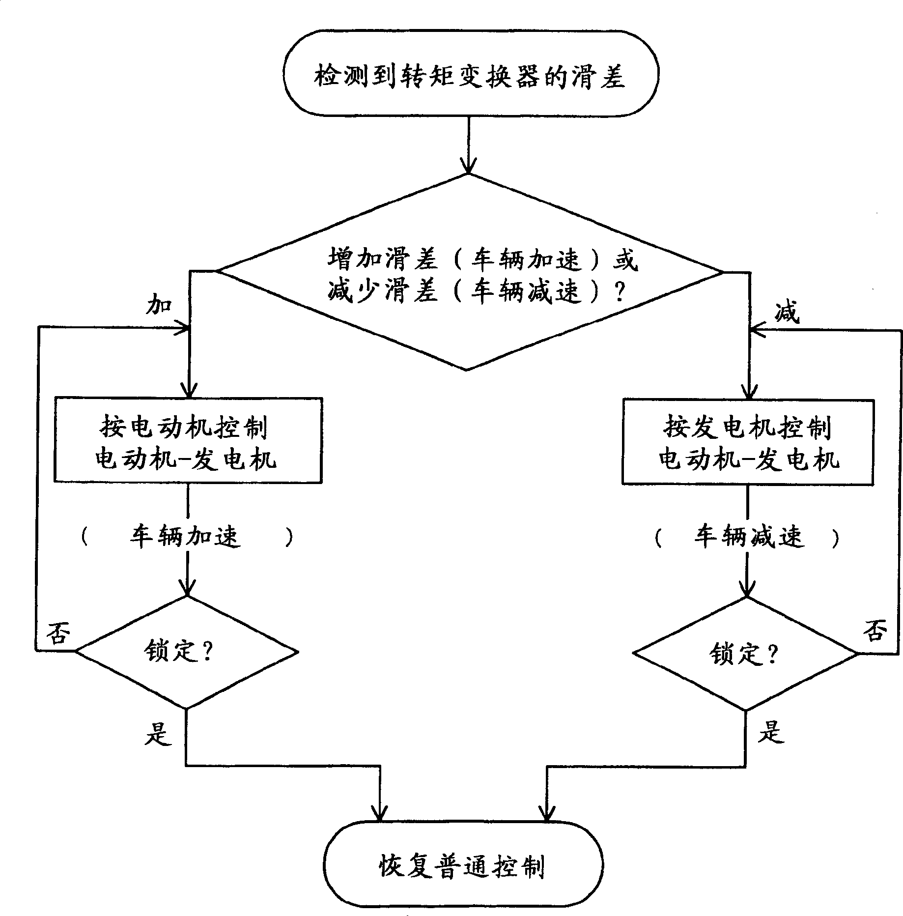
A rotary shaft of a motor-generator of a hybrid-powered vehicle is connected to an output shaft of a torque converter (2) connected to an output shaft of an internal combustion engine (1). A control of acceleration or deceleration of the vehicle is assisted by controlling the motor-generator as a motor or a generator during a time period in which a slip occurs in the torque converter with a speed change control.

Description

technical field [0001] The invention relates to a hybrid vehicle equipped with an internal combustion engine and a motor-generator. The present invention relates to a technique for realizing a hybrid vehicle in which an internal combustion engine and a motor-generator are mounted as power sources on a vehicle having a power transmission system including a torque converter and a multi-stage transmission. The present invention relates to improving the driving performance of a hybrid vehicle and reducing energy loss due to the vehicle's torque converter. Background technique [0002] In order to effectively utilize the torque of the vehicle's internal combustion engine as its power source over a wide speed range, a transmission is provided between the power source and the axle. In addition, cars with automatic transmissions that do not require a clutch pedal to change gears while driving are becoming more and more popular, and almost all drivers today are familiar with such au...

Claims


Application Information

Patent Timeline
Patent Type & Authority Applications(China)
IPC IPC(8): B60W20/00B60K6/485B60K6/547B60K17/04B60L50/16B60W10/04B60W10/08B60W10/10B60W10/11F16H59/46F16H61/14
CPCB60W10/10F16H2061/0433B60K6/48B60K6/547B60L2240/486F16H2063/506B60W20/00B60W2520/105F16H2059/467B60W2510/0241F16H2061/145F16H61/14B60W10/08Y02T10/6221Y02T10/62B60W20/15
Inventor 山口公一
Owner HINO MOTORS LTD
Learn More