Spiral fluorescent light tube

A fluorescent tube, spiral type technology, applied in the field of spiral fluorescent tubes, can solve the problems of limited application, long arc length, affecting the rapid establishment of luminous flux, etc.

Inactive Publication Date: 2004-09-22
GUANGZHOU DOUBLE & TRIPLE LIGHTING APPLIANCES
View PDF0 Cites 1 Cited by
  • Summary
  • Abstract
  • Description
  • Claims
  • Application Information

AI Technical Summary

Problems solved by technology

Falling into another spiral coil facing the starting point with a phase difference of 180°, the arc length is very long, thus affecting the rapid establishment of luminous flux
Because the spiral fluorescent lamp can not solve the problem that the temperature of the cold end and the arc is too long to affect the rapid establishment of the luminous flux, it limits its wider application in the field of lighting

Method used


Image

  • Spiral fluorescent light tube
  • Spiral fluorescent light tube
  • Spiral fluorescent light tube

Examples


Embodiment Construction

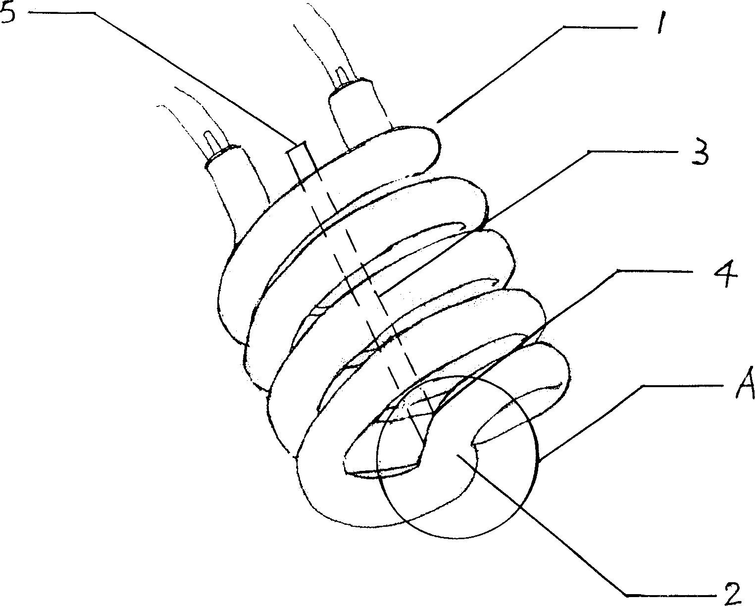
[0008] Such as figure 1 As shown, place one end of the glass tube at the cold end 3 within the range of the top 2 of the spiral fluorescent tube 1, drill a hole in the connecting part 4 of the lamp tube and then seal and connect the cold end tube 3 with the lamp tube 1. When connecting, ensure that the cold The glass tube at end 3 is unimpeded with lamp tube 1.

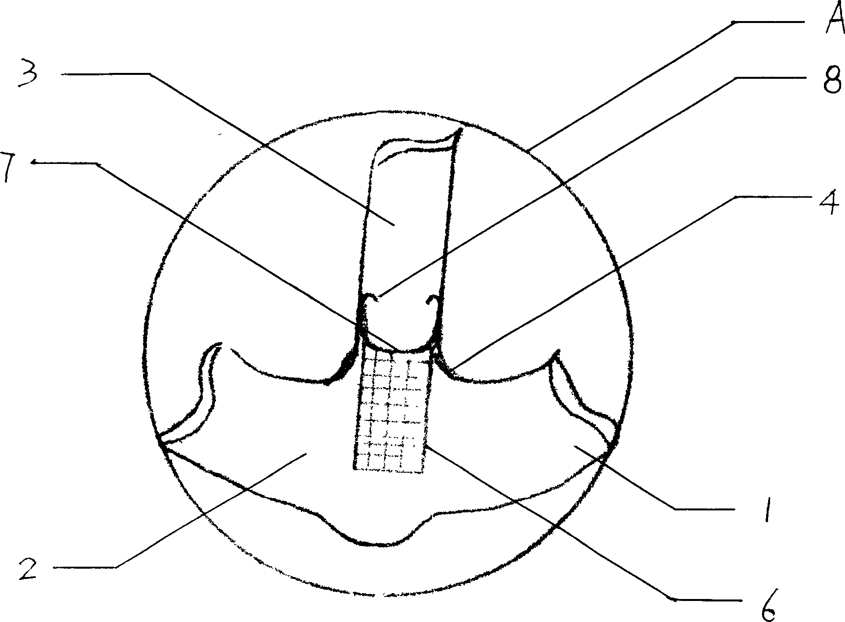
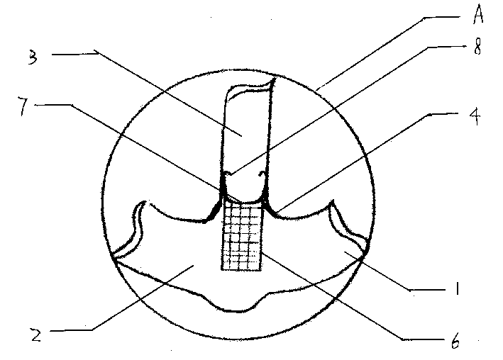
[0009] figure 2 yes figure 1 The expansion diagram of A. After the auxiliary amalgam 6 is connected with the guide wire 8 through the joint 7, the auxiliary amalgam 6 is placed in the lamp tube at the top 2 of the spiral fluorescent tube 1, and the guide wire 8 is placed in the glass tube of the connecting cold end 3, For fixing auxiliary amalgam6. The other end 5 of the connected cold end 3 glass tube is sealed. Since the important photoelectric parameters such as the operating voltage (tube voltage) and luminous efficiency of fluorescent lamps are closely related to the mercury pressure in the tube, the optimu...


PUM


Abstract

The present invention discloses a helical fluorescence lamp tube, on the top of which is provided cooling end 3 of connecting type constituted of glass tube with auxiliary amalgam 6. One end of it is communicated with lamp tube 1, auxiliary amalgam 6 is placed in top tube 2 of the lamp tube via cooling end 3 and fixed with conductive wire 8, and the other end is sealed. Cooling end 3 provided independently in the invention is positioned in the best temperature and position, so that the mercury vapor in the lamp tube can be adjusted in the best state. The provision of auxiliary amalgam 6 speeds the set-up of the luminous flux of the lamp tube effectively to meet the application requirements of the helical fluorescence lamp in a larger illumination range.

Description

technical field [0001] The invention relates to a spiral fluorescent lamp tube. Background technique [0002] Since the invention of the compact fluorescent lamp in the 1980s, it has been vigorously promoted due to its high luminous efficiency, long life, compact structure, and energy saving. In particular, the spiral fluorescent tube has become one of the main light sources for indoor and outdoor lighting because of its more compact structure, firmer structure, reduced light loss, and excellent light distribution curve distribution. However, due to the compact structure, the current density of the lamp tube increases, thereby increasing the electron density, causing the tube temperature to rise, and the mercury pressure in the lamp tube deviates from the optimal value of the cold end, so that the lamp power and lumens are significantly reduced, especially in the whole world. When working in a closed lampshade, the lamp power and lumens drop even more, reaching more than 20...

Claims


Application Information

Patent Timeline
IPC IPC(8): H01J61/24H01J61/30
Inventor 黄甜仔
Owner GUANGZHOU DOUBLE & TRIPLE LIGHTING APPLIANCES
Why Eureka
Try Eureka