Cooking device

A technology of cooking equipment and cooking cavity, which is applied in lighting and heating equipment, household heating, heating fuel, etc., and can solve problems such as inability to transfer heat energy, lower heating efficiency, unpleasant noise, etc.

Inactive Publication Date: 2004-09-29
SAMSUNG ELECTRONICS CO LTD
View PDF0 Cites 13 Cited by
  • Summary
  • Abstract
  • Description
  • Claims
  • Application Information

AI Technical Summary

Problems solved by technology

As a result, heating efficiency is reduced and sufficient thermal energy cannot be transferred to the lower surface of the food, thereby increasing power consumption
In addition, since the heat energy transmitted to the upper and lower portions of food is different from each other, the food must be turned over regularly to cook the upper and lower portions of the food evenly, thereby causing inconvenience to the user
In addition, since the temperature of a portion of the microwave oven surrounding the lower heater becomes extremely high, a cooling fan operating at a high speed must be provided in the microwave oven to cool the heated portion, resulting in unpleasant noise due to the high-speed operation of the cooling fan
[0007] In addition, since the tray separated from the lower heater of conventional cooking equipment has an uneven temperature distribution between its upper surface and the lower surface facing the lower heater, food placed on the tray cannot be cooked evenly.

Method used


Image

  • Cooking device
  • Cooking device
  • Cooking device

Examples


Embodiment Construction

[0035] Embodiments of the present invention will be described in detail below in the drawings, wherein like reference numerals indicate like elements. The following embodiments are intended to explain the present invention with reference to the drawings.

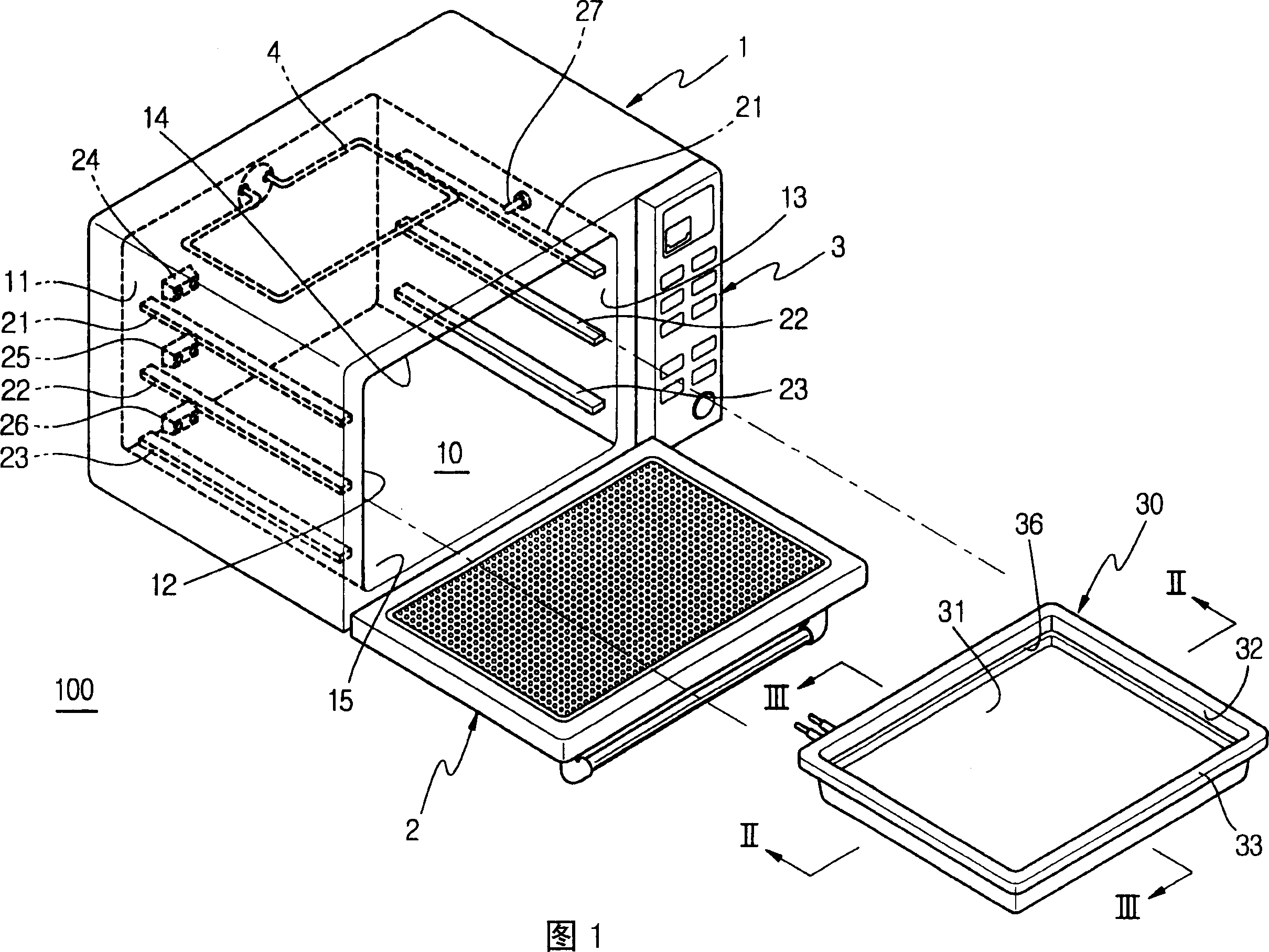
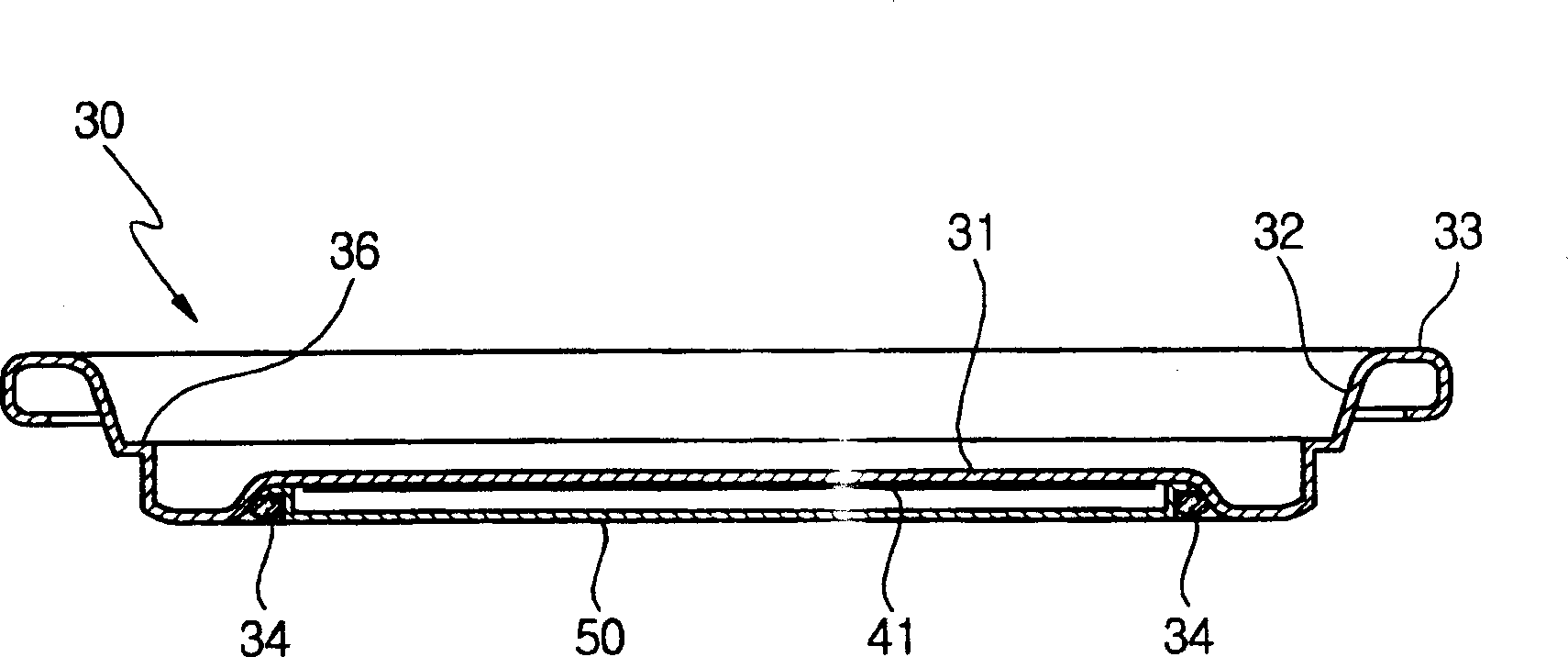
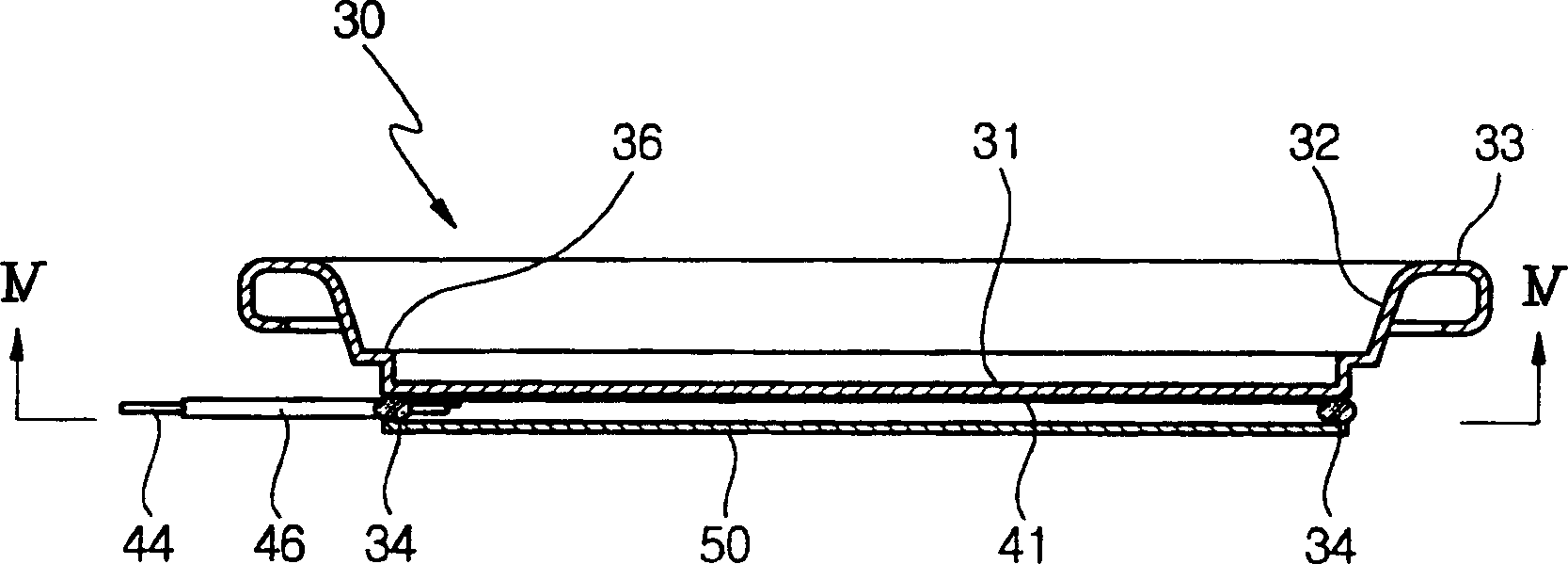
[0036] FIG. 1 is a perspective view showing a cooking apparatus 100 provided with a tray having a heater according to an embodiment of the present invention. The cooking device 100 includes a housing 1 providing an appearance of the cooking device 100, a cooking cavity 10 in the housing 1, a door 2 that opens and closes a front surface of the cooking cavity 10, and a control panel 3 attached near the door 2. on the front surface of the housing 1.

[0037] The cooking chamber 10 is defined by a rear wall 11 , a left wall 12 , a right wall 13 , a top wall 14 and a bottom wall 15 . The cooking cavity 10 is provided with a heater 4 near the top wall 14 and on the rear wall 11 to radiate high temperature heat downward.

[0038...


PUM


Abstract

A cooking apparatus to improve heating efficiency and to quickly cook food. The cooking apparatus includes a heater provided at a tray receiving food to be cooked and having a pair of terminals to supply power to the heater, and a plurality of sockets provided at a rear wall of a cooking cavity. When the tray is placed on a pair of support rails of the cooking cavity and the terminals of the heater are inserted into one of the sockets, the tray is directly heated by the heater to cook the food. The heater includes a conductive film coated on a lower surface of the tray, and first and second electrodes connected to the conductive film to be opposed to each other and connected to the terminals. The conductive film and the tray are heated by current flowing through the conductive film between the first and second electrodes.

Description

technical field [0001] The present invention relates to a cooking device, in particular to a cooking device comprising a power socket and a tray, wherein the power socket is arranged on the rear wall of the cooking cavity of the cooking device, and a heater is provided in the tray, so that Heat is generated on the tray by the heater to improve heating efficiency. Background technique [0002] Generally, a cooking device includes a cooking cavity for receiving food to be cooked and a heating device installed in the cooking cavity or in an additional chamber isolated from the cooking cavity. For example, a microwave oven as a cooking device includes a cooking chamber defining a space for cooking food therein, and a machine chamber separated from the cooking chamber, the machine chamber having a magnetron that generates microwaves. Microwaves are then introduced into the cooking cavity to cook the food. [0003] In microwave ovens, where cooking is performed only by microwave...

Claims


Application Information

Patent Timeline
Patent Type & Authority Applications(China)
IPC IPC(8): H05B3/20A47J37/00A47J37/06F24C1/00F24C7/06F24C15/16
CPCF24C7/06F24C15/166F24C15/003A47J37/00
Inventor 小林省三许政义黄允翼赵丰衍高东煜金光根
Owner SAMSUNG ELECTRONICS CO LTD
Why Eureka
Try Eureka