Rotor of synchronous magneto resistance motor

A synchronous reluctance motor and rotor technology, applied in synchronous machines, synchronous motors for single-phase current, magnetic circuit rotating parts, etc., can solve problems such as affecting motor characteristics, reducing motor starting characteristics, etc., to improve starting characteristics. , the effect of improving reliability

Inactive Publication Date: 2004-09-29
LG ELECTRONICS (TIANJIN) APPLIANCES CO LTD
View PDF0 Cites 3 Cited by
  • Summary
  • Abstract
  • Description
  • Claims
  • Application Information

AI Technical Summary

Problems solved by technology

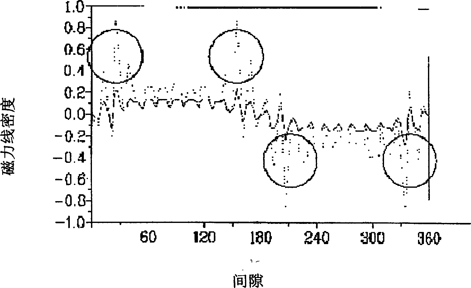
[0010] The distortion of the magnetic line density at the air gap mentioned above seriously affects the characteristics of the motor
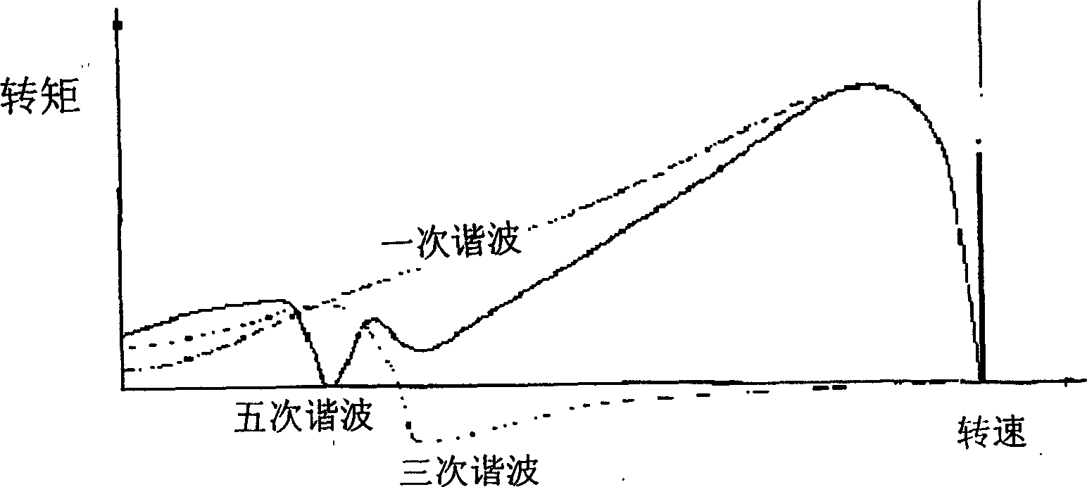
like image 3 As shown, due to the distortion of the magnetic force line density at the air gap, when t

Method used


Image

  • Rotor of synchronous magneto resistance motor
  • Rotor of synchronous magneto resistance motor
  • Rotor of synchronous magneto resistance motor

Examples


Embodiment Construction

[0025] Below in conjunction with accompanying drawing and specific embodiment the present invention is described in further detail:

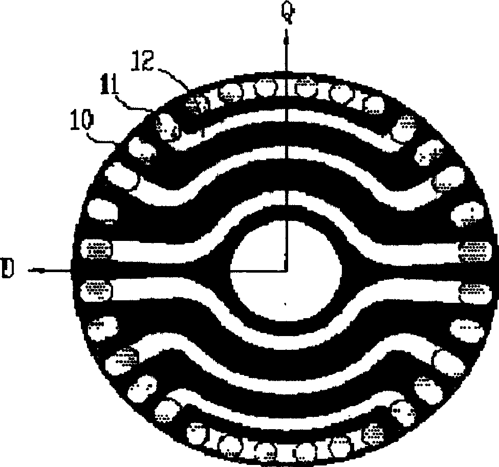
[0026] Figure 4 It is a plan view of the rotor structure of the synchronous reluctance motor of the present invention.

[0027] Figure 5 It is a comparison chart of the simulated experiment data of the starting effect of the existing common synchronous reluctance motor and the synchronous reluctance motor of the present invention after adding a load.

[0028] like Figure 4 As shown, the rotor of the synchronous reluctance motor of the present invention includes: an iron core 10, several conductor bars evenly embedded in the outer peripheral surface of the iron core 10 and several separators 12 inserted into the iron core 10; 12 around the rotor shaft and divided into two groups symmetrical to each other centered on the rotor shaft.

[0029] The conductor rods include: conductor rods 11 embedded in the outer peripheral surface of the iron ...


PUM


Abstract

This invention discloses a rotor of a synchronous reluctance machine including a core, several conducting rods inserted into the outer cycle of the core in uniform space and several blocking plates plugging into the core divided into two symmetrical groups around the shaft-center. The said conducting rods includes: the conducting rods inserting into the outer cycle of the core and connecting with the ends of the blocking plates and deep-inserting rods inserting but not connecting with their ends, the outer surfaces of the rods are just aligned with the peripheral face of the core and the deep-inserting rods deep in the peripheral face of the core forming a certain distance between the two outer surfaces.

Description

technical field [0001] The invention relates to a synchronous reluctance motor, in particular to a rotor of a synchronous reluctance motor Background technique [0002] Synchronous motor is a kind of AC motor. Generally speaking, when the frequency of AC power supply is constant, the speed of synchronous AC motor has nothing to do with the load. That is to say, synchronous AC motor is a uniform speed motor with synchronous speed as the speed. For the synchronous reluctance motor, its torque is generated by the reluctance component. In other words, the rotor of the synchronous reluctance motor rotates by the reluctance torque. [0003] The existing ordinary synchronous reluctance motor generally includes: a stator and a rotor; a coil is arranged on the stator, and the rotor is arranged in a cavity surrounded by the stator; after the stator coil is connected to an alternating current, a rotating magnetic field is formed around the stator, and the rotating magnetic field Under...

Claims


Application Information

Patent Timeline
IPC IPC(8): H02K1/22H02K19/00H02K19/02
Inventor 严载富郑泰旭严相俊朴炯俊
Owner LG ELECTRONICS (TIANJIN) APPLIANCES CO LTD
Why Eureka
Try Eureka