Asynchronous motor optimizing excitation control method based on magnetic-field saturated non-linear motor model

An asynchronous motor, excitation control technology, applied in motor generator control, electronic commutation motor control, control system and other directions, can solve problems such as slow dynamic response, poor load capacity, and control results easily affected by changes in motor parameters.

Inactive Publication Date: 2005-06-15
TSINGHUA UNIV
View PDF0 Cites 0 Cited by
  • Summary
  • Abstract
  • Description
  • Claims
  • Application Information

AI Technical Summary

Problems solved by technology

[0004] (1) Frequency modulation and voltage regulation control: This method is simple to implement and is widely used in occasions that do not require high speed regulation performance. The disadvantages are poor load capacity, slow dynamic response, and worse performance at low speeds;
[0005] (2) Field Oriented Vector Control: This method decouples the excitation current and torque current components of the asynchronous motor to achieve control performance similar to that of a separately excited DC motor; this method can greatly improve the speed regulation performance of the asynchronous motor, and is currently the More control methods are used in high-performance AC speed control systems; the disadvantage is that the magnetic field direction of the motor rotor needs to be detected, and the control results are easily affected by changes in motor parameters;
[0006] (3) Direct torque control: Due to the direct feedback bang-bang control method, coordinate transformation is omitted, the control structure is simplified, and the influence of motor parameter changes is avoided; the disadvantage is that low-speed torque ripple is introduced, which limits speed regulation range, reducing speed governing performance
But at this time, the saturation degree of the main magnetic circuit of the motor will change, and the inductance parameter is no longer a constant, so a new mathematical model and control strategy of the motor must be adopted

Method used


Image

  • Asynchronous motor optimizing excitation control method based on magnetic-field saturated non-linear motor model
  • Asynchronous motor optimizing excitation control method based on magnetic-field saturated non-linear motor model
  • Asynchronous motor optimizing excitation control method based on magnetic-field saturated non-linear motor model

Examples


Embodiment Construction

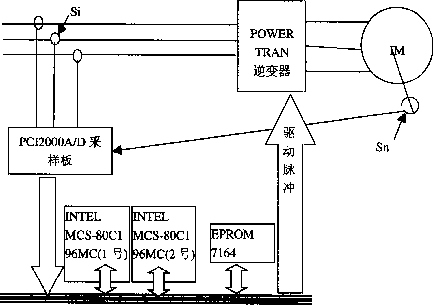
[0154] please see image 3 and Figure 4 .

[0155] First, give the speed given value ω according to the required motor speed * , compare the given value with the measured speed ω r Subtract the speed error Δω, and then substitute the speed error into the speed PI regulator to calculate the torque reference value Te * ;At the same time according to the actual speed and torque reference value Te * , from the already calculated excitation optimization curve look-up table to get the required optimal excitation current reference value i * Ms , and at the same time substitute the given excitation current into the torque current calculation module to calculate the given torque current i from formulas (3) and (4) * Ts ; The required slip frequency ω can be calculated by the formula (5) through the given excitation and torque current s , plus the actual measured motor speed ω r Obtain the angular frequency of the rotor current; calculate the integral calculation of the angula...


PUM


Abstract

The present invention belongs to the field of asynchronous motor exciting speed-regulating technology and features the exciting speed-regulating method of optimizing stator-exciting current to regulate rotor magnetic linkage. It MT coordinate system, the finite element analysis to asynchronous motor magnetic field is performed to obtain the effect of saturated motor magnetic field on motor parameters and the stator and rotor magnetic linkage via solving non-linear equation. The magnetic linkage table is optimized to obtain optimized exciting table and maximum torque vs rotation speed table. By means of PI control method to obtain optimized exciting current and reference value of torque current, comparison to practical exciting current and torque current and PI regulation and voltage decoupling, final stator voltage in MT coordinate system is obtained for the control of the inverter.

Description

Technical field [0001] The invention relates to an asynchronous motor optimal excitation method based on a nonlinear motor model of magnetic field saturation, which belongs to the technical field of excitation control of asynchronous motor speed. Background technique [0002] With the development of power electronics technology and computer technology, AC electric drive is gradually replacing DC drive to become the main trend of electric drive. Among AC motors, asynchronous motors are the most widely used, and their advantages are low cost, simple structure, high reliability, convenient maintenance, small moment of inertia, high efficiency, and large rated capacity. However, AC motors, especially asynchronous motors, are multivariable and strongly coupled systems. The control system is very complicated and it is difficult to achieve high-performance speed regulation. Various testing instruments are often used to participate in the control, which increases the complexity and ...

Claims


Application Information

Patent Timeline
Patent Type & Authority Patents(China)
IPC IPC(8): H02P21/00
Inventor 朱东起姜新建宇文博许德伟
Owner TSINGHUA UNIV
Why Eureka
Try Eureka