Valve control apparatus for IC engine

A control device and valve control technology, applied in valve device, engine control, fuel injection control, etc., can solve the problems of reducing weight and manufacturing cost, reducing fuel economy, increasing power consumption, etc., to improve power output, improve Fuel economy, energy saving effect

Inactive Publication Date: 2004-09-29
HONDA MOTOR CO LTD
View PDF5 Cites 7 Cited by
  • Summary
  • Abstract
  • Description
  • Claims
  • Application Information

AI Technical Summary

Problems solved by technology

This reduces fuel economy due to increased power consumption, and cannot achieve improved fuel economy and higher rpm and higher power output in a compatible manner, or significantly reduced weight and manufacturing costs
Also, for this valve control device, in order to install a solenoid, an armature, and a shock absorbing spring therein, it is necessary to change the design of the cylinder head and the suction valve, which inevitably requires a high cost

Method used


Image

  • Valve control apparatus for IC engine
  • Valve control apparatus for IC engine
  • Valve control apparatus for IC engine

Examples


Embodiment Construction

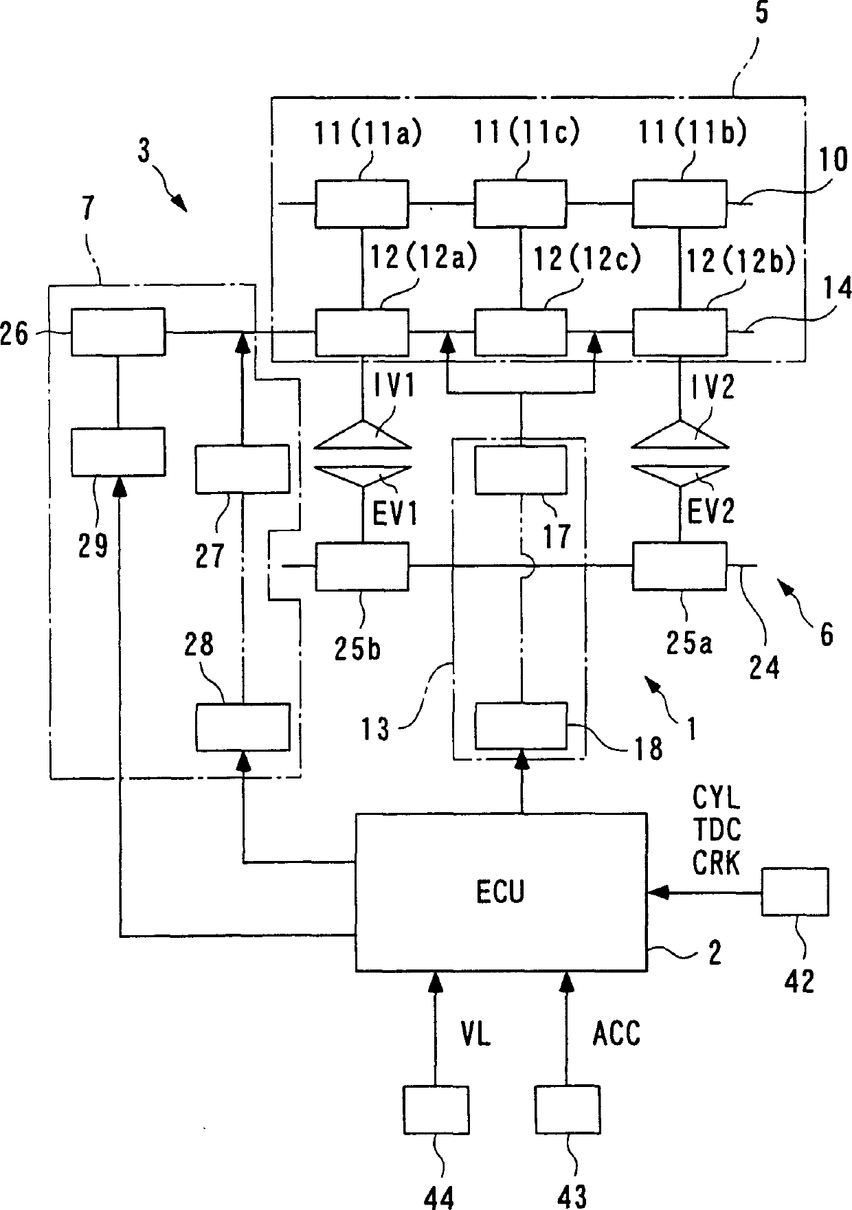
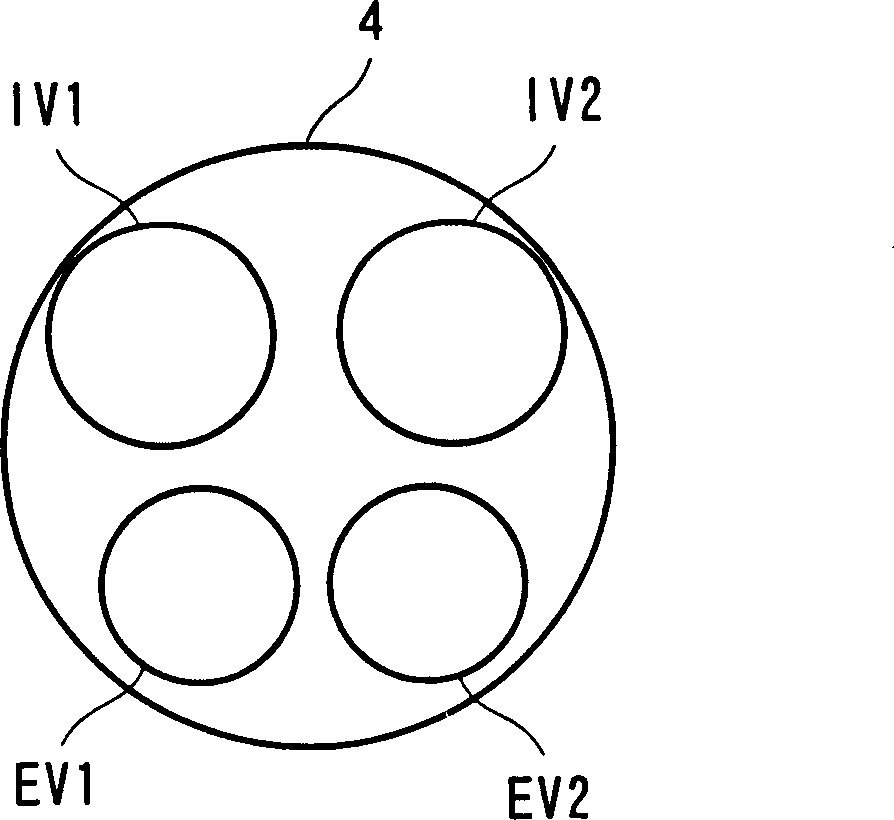
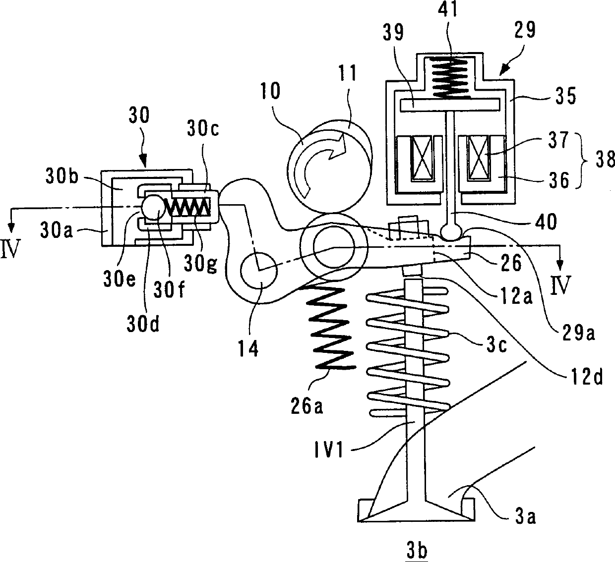
[0057] A valve control device for an internal combustion engine according to an embodiment of the present invention will be described below with reference to the drawings. Fig. 1 schematically shows the structure of a valve control device to which the present invention is applied. An internal combustion engine (hereinafter referred to as "engine") 3 shown therein is a four-cylinder (only one cylinder is shown in FIG. 2 ) in-line DOHC engine mounted on a vehicle not shown. As shown in FIG. 2, each cylinder 4 is provided with first and second intake valves IV1, IV2 and first and second exhaust valves EV1, EV2 as engine valves. As shown in FIG. 3 showing an example of the first suction valve IV1, the suction valves IV1, IV2 are arranged such that they can respectively be in the closed position (shown in FIG. 3 ) for closing the suction port 3a of the engine 3 and an open position (not shown) for opening the suction port 3a, in which the suction valve protrudes into the combustio...


PUM


Abstract

A valve control apparatus for an internal combustion engine is provided which is capable of optimally setting the closing timing of an engine valve according to operating conditions of the engine while suppressing an increase in the inertial mass of the engine valve to the minimum, thereby attaining improvement of fuel economy, and realization of higher engine rotational speed and higher power output in a compatible fashion, and reducing costs and weight thereof. The valve control apparatus controls opening and closing operations of an engine valve. A cam-type valve actuating mechanism actuates the engine valve to open and close the engine valve, by a cam which is driven in synchronism with rotation of the engine. An actuator makes blocking engagement with the engine valve having been opened, to thereby hold the engine valve in an open state. An ECU controls operation of the actuator to thereby control closing timing of the engine valve.

Description

technical field [0001] The present invention relates to a valve control device for controlling the opening and closing operation of a suction valve and / or an exhaust valve, in particular for controlling the valve closing timing. Background technique [0002] In general, in order to improve the fuel economy and power output of an internal combustion engine and to reduce exhaust emissions of the internal combustion engine, various valve control devices have been proposed which variably control the opening and closing of an intake valve and / or a control valve Timing, or valve lift, in order to adapt the intake and exhaust performance to the operating conditions of the engine. As one such general valve control device, a known type is to change the phase of the intake cam relative to the camshaft, thereby continuously changing the opening and closing timing of the intake cam (for example, Japanese Patent Laid-Open No. Hei 7-301144) . However, in this valve control device, the s...

Claims


Application Information

Patent Timeline
Patent Type & Authority Applications(China)
IPC IPC(8): F01L1/18F01L1/26F01L9/04F01L13/00F02D13/02F02D41/04F02D41/06F02D45/00
CPCF01L1/267F01L1/022Y02T10/18F01L2800/00F01L13/0036F01L13/0005F01L13/00
Inventor 酒井久夫清水康雄八卷利宏小泽英隆
Owner HONDA MOTOR CO LTD
Why Eureka
Try Eureka