Color solid photographic device

A solid-state imaging element, solid-state technology, applied in cooling fluid circulation devices, solid-state image signal generators, color TVs, etc., can solve the problems of inability to achieve high sensitivity, uneven pixel configuration, and uneven image density.

Inactive Publication Date: 2004-10-13
PANASONIC SEMICON SOLUTIONS CO LTD
View PDF1 Cites 15 Cited by
  • Summary
  • Abstract
  • Description
  • Claims
  • Application Information

AI Technical Summary

Problems solved by technology

However, since pixels that are not subject to pixel mixing exist within the effective area of ​​the solid-state imaging device, it is unfortunate that high sensitivity cannot be achieved.
In addition, as a result of uneven arrangement of the reduced number of pixels for each color obtained by mixing, there is a problem of unevenness in the image.

Method used


Image

  • Color solid photographic device
  • Color solid photographic device
  • Color solid photographic device

Examples


no. 1 Embodiment approach

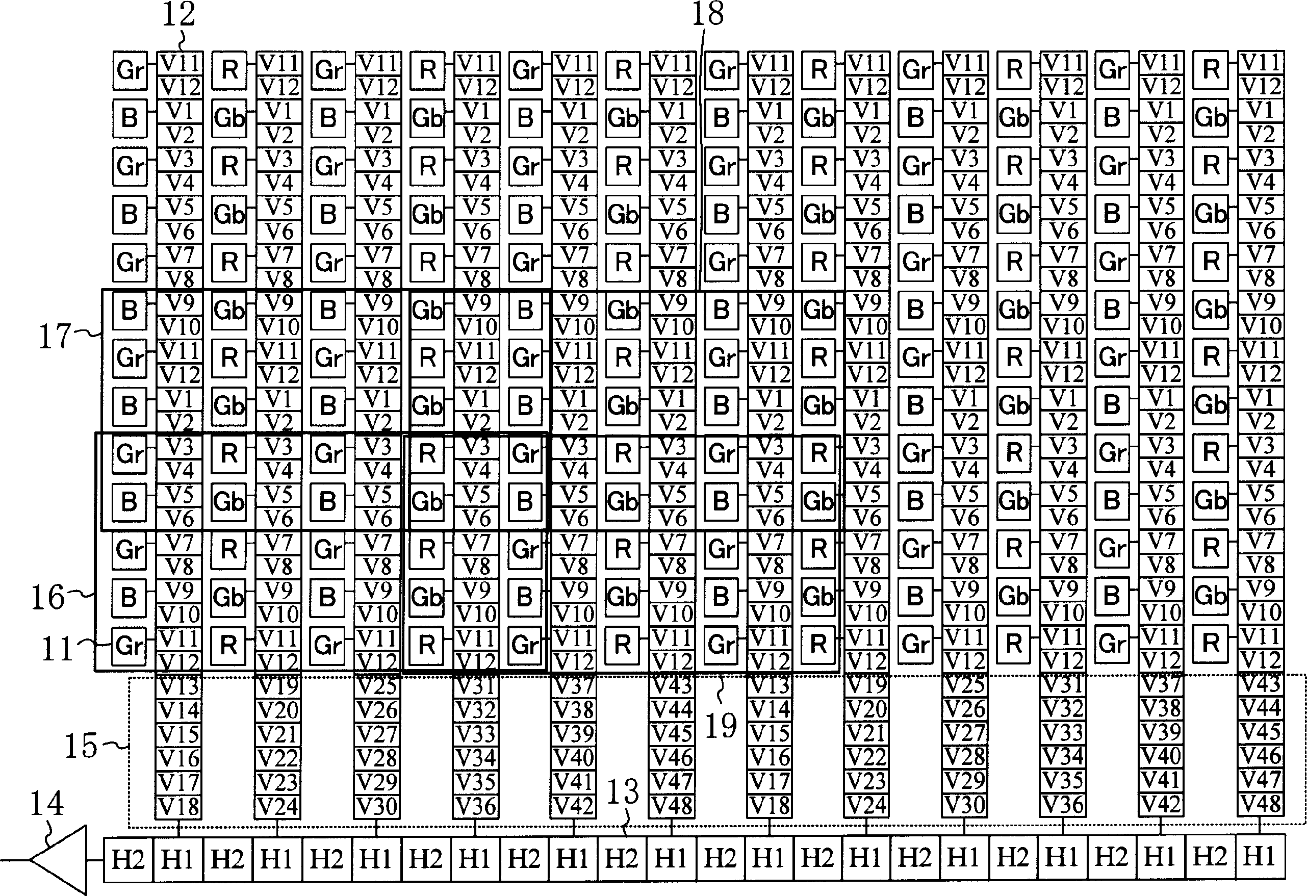
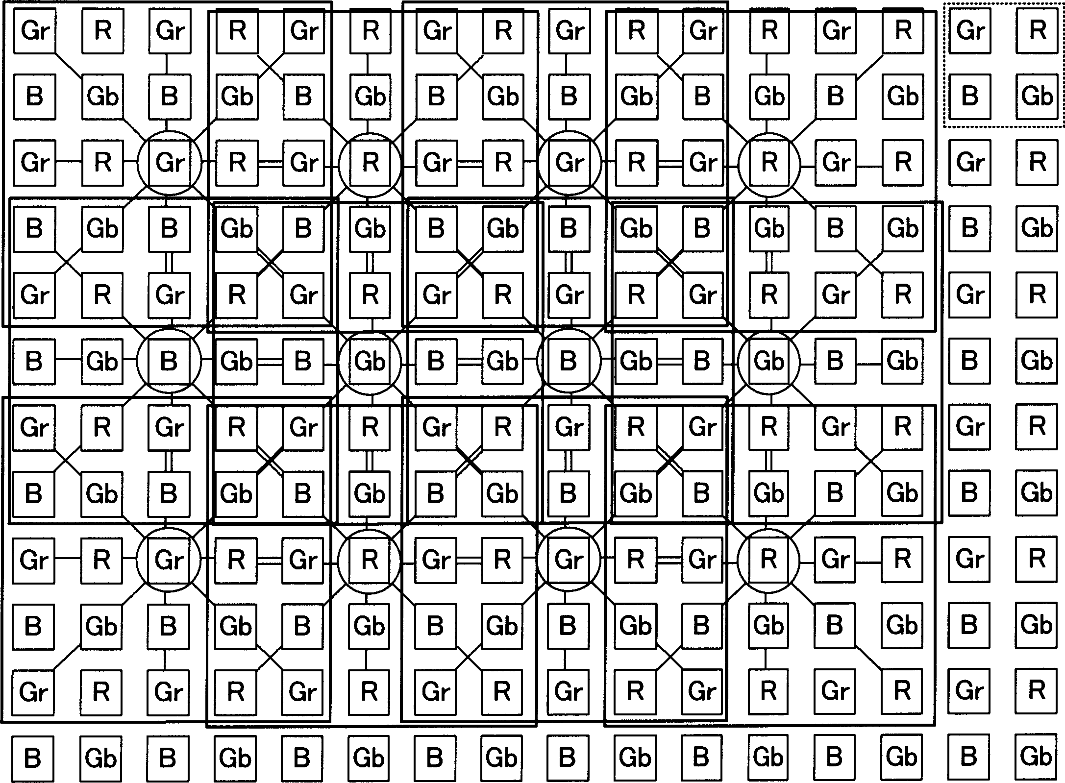
[0062] figure 1 , is a configuration diagram of the CCD solid-state imaging device according to the first embodiment of the present invention. 11 is a photoelectric conversion element and a color filter installed in front of it. Here, for example, the color filters are arranged in a Bayer arrangement. Here, color filters of R (Red: red), G (Green: green), and B (Blue: blue) are used. Gr and Gb are actually the same color (green), but for the convenience of explaining the action, the color filter pixels sandwiched by R color filters on both horizontal sides are recorded as Gr, and the filter pixels sandwiched by B color filters on both horizontal sides Color pixels are recorded as Gb. 12 is a 12-phase vertical transmission section composed of V1 to V12, 13 is a 2-phase horizontal transmission section composed of H1 and H2, 14 is an output amplifier, 15 is an extension of the above-mentioned 12-phase vertical transmission section 12 composed of V1 to V12, The gate is connect...

no. 2 Embodiment approach

[0074] Figure 5 , is a configuration diagram of a CCD solid-state imaging element of a second embodiment of the color solid-state imaging device of the present invention. 51 is a photoelectric conversion element and a color filter installed in front of it. Here, the color filter array is arranged in a two-way spaced arrangement of, for example, 2 rows and 4 columns. 52 is a 12-phase vertical transmission section composed of V1 to V12, 53 is a three-phase horizontal transmission section composed of H1 to H3, 54 is an output amplifier, and 55 is an extension of the 12-phase vertical transmission section 52 composed of V1 to V12. The gate is connected separately, and the vertical-horizontal transmission control part is composed of V13 to V48. 56 is the basic unit of the Mg pixel mixing area, 57 is the basic unit of the G pixel mixing area, and 58 is the basic unit of the Ye pixel mixing area. Unit, 59 is the basic unit of the pixel mixing area of ​​Cy. The basic units 56 to 5...

no. 3 Embodiment approach

[0087] Figure 7 , is a configuration diagram of a CCD solid-state imaging element of a third embodiment of the color solid-state imaging device of the present invention. 71 is a photoelectric conversion element and a color filter installed in front of it. Here, for example, color filters are arranged in a Bayeux arrangement. 72 is an 8-phase vertical transmission section composed of V1 to V8, 73 is a 2-phase horizontal transmission section composed of H1 and H2, 74 is an output amplifier, 75 is an extension of the above-mentioned 8-phase vertical transmission section 72 composed of V1 to V8, The gate is connected separately, and the vertical-horizontal transmission control part composed of V9 to V24, 76 is the basic unit of the pixel mixing area of ​​Gr, 77 is the basic unit of the pixel mixing area of ​​B, and 78 is the basic unit of the pixel mixing area of ​​Gb Unit, 79 is the basic unit of R's pixel blending region. Each of the basic units 76 to 79 in the pixel mixing ...


PUM


Abstract

To solve problems of a conventional moving picture photographing using a high pixel density color solid-state imaging element that reflected noise intruded to a low frequency region of a high frequency video signal due to resampling is unavoidable and the effective sensitivity is remarkably deteriorated through aborted pixel signals although interleaved pixel reading represented by pixel interleaving in the vertical direction is generally employed. Pixel areas of the high pixel density color solid-state imaging element are divided into areas in units of pixel mixture, and all pixels in the same color are respectively mixed in each of the area divisions (16 to 19) to increase the pixel utilizing rate to 100%, and the spatial LPF effect of area pixel mixing remarkably suppresses the intrusion of reflected noise to the low frequency region of the high frequency video signal.

Description

technical field [0001] The present invention relates to color solid-state imaging devices for digital still cameras, digital video cameras and the like. Background technique [0002] Conventionally, solid-state imaging devices that convert received optical signals into electrical signals and output them as video signals are well known, and video cameras such as digital still cameras that display video signals obtained from this solid-state imaging device as still images are also known to every household. In recent years, video cameras using such a solid-state imaging device have higher requirements for image quality and performance, and improvement in image quality has been rapidly developed. [0003] For example, as long as it is a solid-state imaging device with 5 million pixels, the number of pixels in the vertical direction is about 1920 pixels, and the number of pixels in the horizontal direction is about 2560 pixels. The number of pixels is about 16 times higher than ...

Claims


Application Information

Patent Timeline
Patent Type & Authority Applications(China)
IPC IPC(8): H01L27/148H01L27/146H01L31/10H04N5/335H04N5/341H04N5/367H04N5/369H04N5/3722H04N5/378H04N9/04H04N9/07
CPCH04N3/1562H04N5/23245H04N9/045H04N23/667H04N25/46H04N25/73H04N25/136H04N25/134F25D31/002B67D2001/0093F25D2400/38
Inventor 藤井俊哉岩泽高广山口琢己村田隆彦
Owner PANASONIC SEMICON SOLUTIONS CO LTD
Why Eureka
Try Eureka