Rear-view mirror for vehicle

A technology for rear-view mirrors and vehicles, applied in the field of rear-view mirrors for vehicles, can solve the problems of large gap between the shell and the lens, easy deformation of the lens, etc., and achieve the effect of enhancing impact resistance and avoiding deformation.

Inactive Publication Date: 2004-10-20
EXON SCIENCE INC
View PDF0 Cites 9 Cited by
  • Summary
  • Abstract
  • Description
  • Claims
  • Application Information

AI Technical Summary

Problems solved by technology

[0004] The object of the present invention is to provide a rearview mirror for vehicles, which solves the defects in the prior art that the gap between the housing and the lens is too large and the lens is easily deformed

Method used


Image

  • Rear-view mirror for vehicle
  • Rear-view mirror for vehicle
  • Rear-view mirror for vehicle

Examples


Embodiment Construction

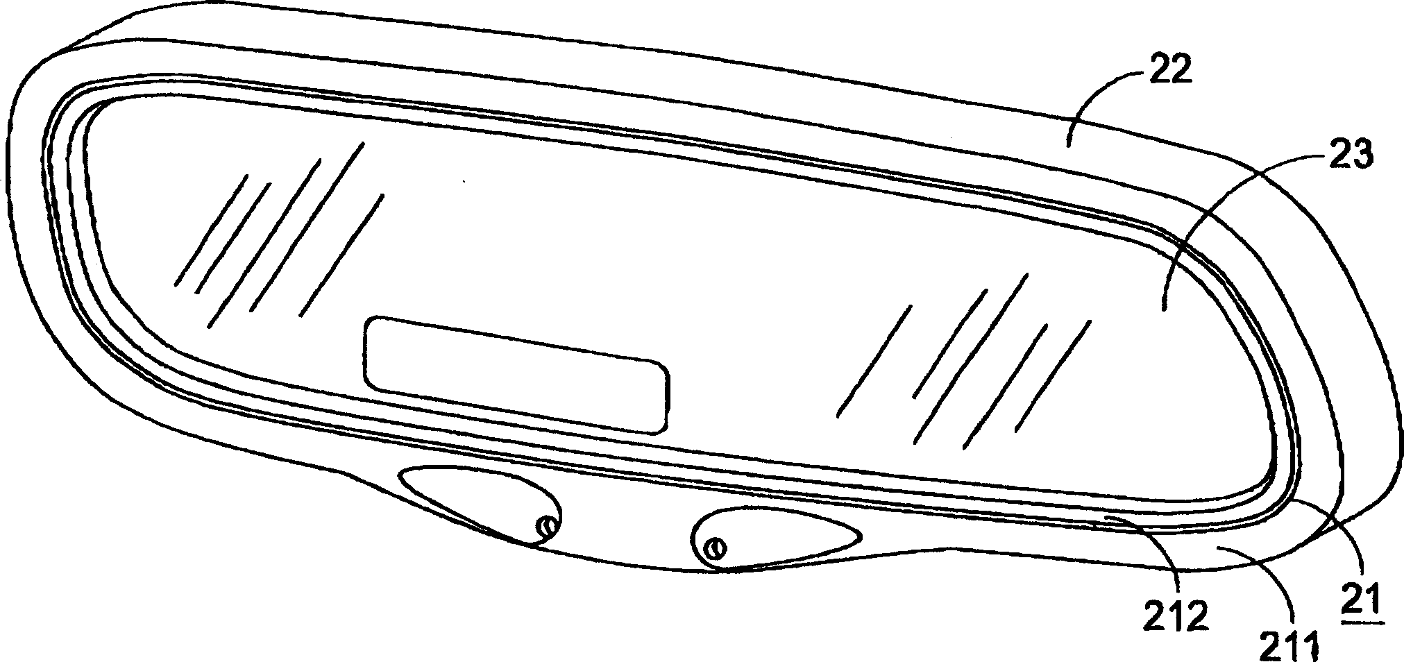
[0039] Please see Figure 2(a) and Figure 2(b). A vehicle rearview mirror of the present invention includes a front housing 21 , a rear housing 22 , and a lens 23 . When assembling, the lens 23 is put into the rear case 22 through the opening 220 , and then the front case 21 is placed on the lens 23 and combined with the rear case 22 . The combination of the front case 21 and the rear case 22 can be done by gluing, fitting, welding or any other suitable way, depending on the materials to be combined. The material of the rear shell is different according to the requirements of practicability and aesthetics, for example, it can be plastic, rubber, resin, metal material, carbon fiber or wood. Preferably, the rear shell material is made of an engineering material, such as nylon (nylon), PBT, PC, ABS, HI-PS, PP, LCP, PE or PS, and is also suitable for materials such as magnesium alloy and carbon fiber. Made. When nylon is used as the material of the rear shell, glass fibers can b...


PUM


Abstract

A rear-view mirror is composed of a morror, the first shell made of the first material for holding said mirror and the second shell made of the second material and arranged between the first shell and said mirror. The flexible of the second material is higher than that of the first one, resulting in close connection between shall and mirror.

Description

technical field [0001] The invention relates to a vehicle rearview mirror, in particular to a vehicle rearview mirror with a compound shell structure. Background technique [0002] Please refer to Fig. 1 (a) and Fig. 1 (b), it is the three-dimensional and exploded view of a known interior rearview mirror respectively, and this rearview mirror structure comprises a front housing 11, a rear housing 12, and a A lens 13 located between the front and rear shells 11 and 12 . The front and rear housings 11 and 12 are generally made of a rigid plastic material, such as polycarbonate (polycarbonate; PC) or acrylonitrile-butadiene-styrene (acrylonitrile-butadiene-styrene; ABS) resin. system, in order to fix the lens 13 therebetween. Since the casing and the lens are not elastic, it is difficult to be completely sealed therebetween. In other words, there may be a large gap between the housing and the lens. Therefore, the impact resistance of the lens 13 will be affected. In additi...

Claims


Application Information

Patent Timeline
Patent Type & Authority Applications(China)
IPC IPC(8): B60R1/04B60R1/06
CPCB60R1/04B66B5/24B66B5/044
Inventor 苏文威陈奎宏
Owner EXON SCIENCE INC
Why Eureka
Try Eureka