Method for producing joint between corrugated tube and coupling

A connecting piece and corrugated technology, applied in the field of connection generation, can solve problems such as high equipment cost, and achieve the effect of low cost, small size and compact connection structure

Active Publication Date: 2004-10-20
布鲁格罗尔控股公司
View PDF3 Cites 8 Cited by
  • Summary
  • Abstract
  • Description
  • Claims
  • Application Information

AI Technical Summary

Problems solved by technology

This connection requires high equipment costs at the assembly site and presupposes thick-walled formed parts

Method used


Image

  • Method for producing joint between corrugated tube and coupling

Examples


Embodiment Construction

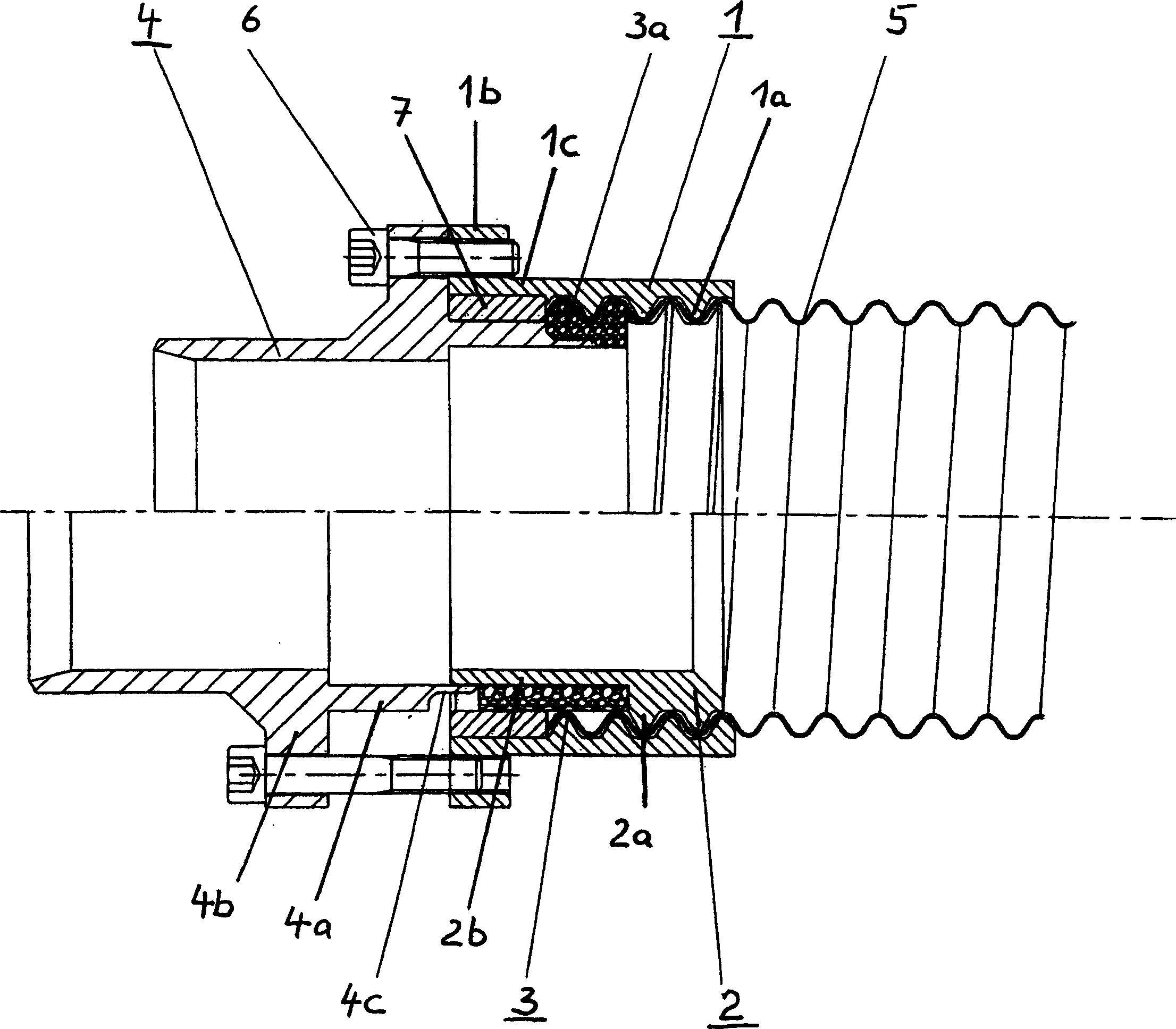
[0016] First, the support ring 2 is screwed with its coarse-pitch thread 2 a into the smooth end of the bellows 5 to such an extent that a part of the smooth wall region 2 b protrudes beyond the end of the bellows 5 . A graphite sealing ring 3 is put on the light wall part 2b, the length of this sealing ring is slightly shorter than the length of the light wall part 2b.

[0017] A compression ring 1 is screwed onto the bellows 5 by means of its coarse-pitch thread 1 a such that the last thread ends at the end of the bellows 5 and the bare area 1 c extends beyond the end of the bellows.

[0018] A metal pipe 7 is arranged on the sealing ring 3 .

[0019] The connecting part 4 has a projection 4a, which can be slid into the annular gap between the bellows 5 and the bare wall portion 2b.

[0020] The flanges 4 b , 1 b are brought closer to each other by means of fastening screws 6 , which are passed through holes, not shown in detail, in the flange 4 b of the connecting part 4 a...


PUM


Abstract

A method of producing a joint between the end of a helically corrugated metal tube and a coupling, whereby a support ring (2) is screwed into the end of the helically corrugated metal tube until a smooth walled area (2b) remains both inside the metal tube and also protrudes from its end. A thrust collar (1) is screwed onto the end of the metal tube so that a smooth walled area (1c) of the thrust collar (1), which is equipped with a flange (1b), protrudes from the end of the metal tube. A graphite sealant ring (3) is inserted into the end of the metal tube where it is axially and radially deformed and compressed by the action of clamping bolts (6), which are inserted into holes in the flange (1b) of the thrust collar (1) and a flange (4b) of the coupling (4) and clamp the flanges (1b, 4b) together.

Description

technical field [0001] The invention relates to a method of producing a connection between the end of a helically corrugated metal pipe and a connecting piece. Background technique [0002] Various solutions are available for producing the interconnection of metal tubes or for producing a connection between a metal tube and a connecting piece. Therefore, it is common practice to braze or weld the above-mentioned components together or to screw them together. [0003] Joining thin-walled metal tubes to each other or to a fitting is problematic because screwing or welding is difficult due to the thinner walls, and brazing only makes sense for some metals. [0004] It is also possible to adopt a more complex method to complete the connection of the helical thin-walled corrugated metal pipe and the connecting piece. [0005] From CH-PS 589249 it is known that the end of a corrugated metal tube is rolled against the inner surface of a flange, wherein the corrugations are flatte...

Claims


Application Information

Patent Timeline
Patent Type & Authority Applications(China)
IPC IPC(8): F16L1/00F16L33/26
CPCY10T29/49913F16L33/26F16L25/0036Y10T29/49885
Inventor J·霍曼
Owner 布鲁格罗尔控股公司
Why Eureka
Try Eureka