
Adjustable multi-band antenna

A multi-band antenna and antenna technology, applied to antennas, resonant antennas, antenna components, etc., can solve the problems of increased signal loss and reduced antenna efficiency, and achieve the effect of free adjustment of the circuit, free design, and low possibility of ESD)

Inactive Publication Date: 2004-10-20
L K PROD OY
View PDF2 Cites 18 Cited by
  • Summary
  • Abstract
  • Description
  • Claims
  • Application Information

AI Technical Summary

Problems solved by technology

Another disadvantage is that the loss of the signal increases so much in the lower frequency bands that the antenna efficiency in the lower frequency bands decreases, e.g. from 0.5 to 0.4

Method used


Image

  • Adjustable multi-band antenna
  • Adjustable multi-band antenna
  • Adjustable multi-band antenna

Examples


Embodiment Construction

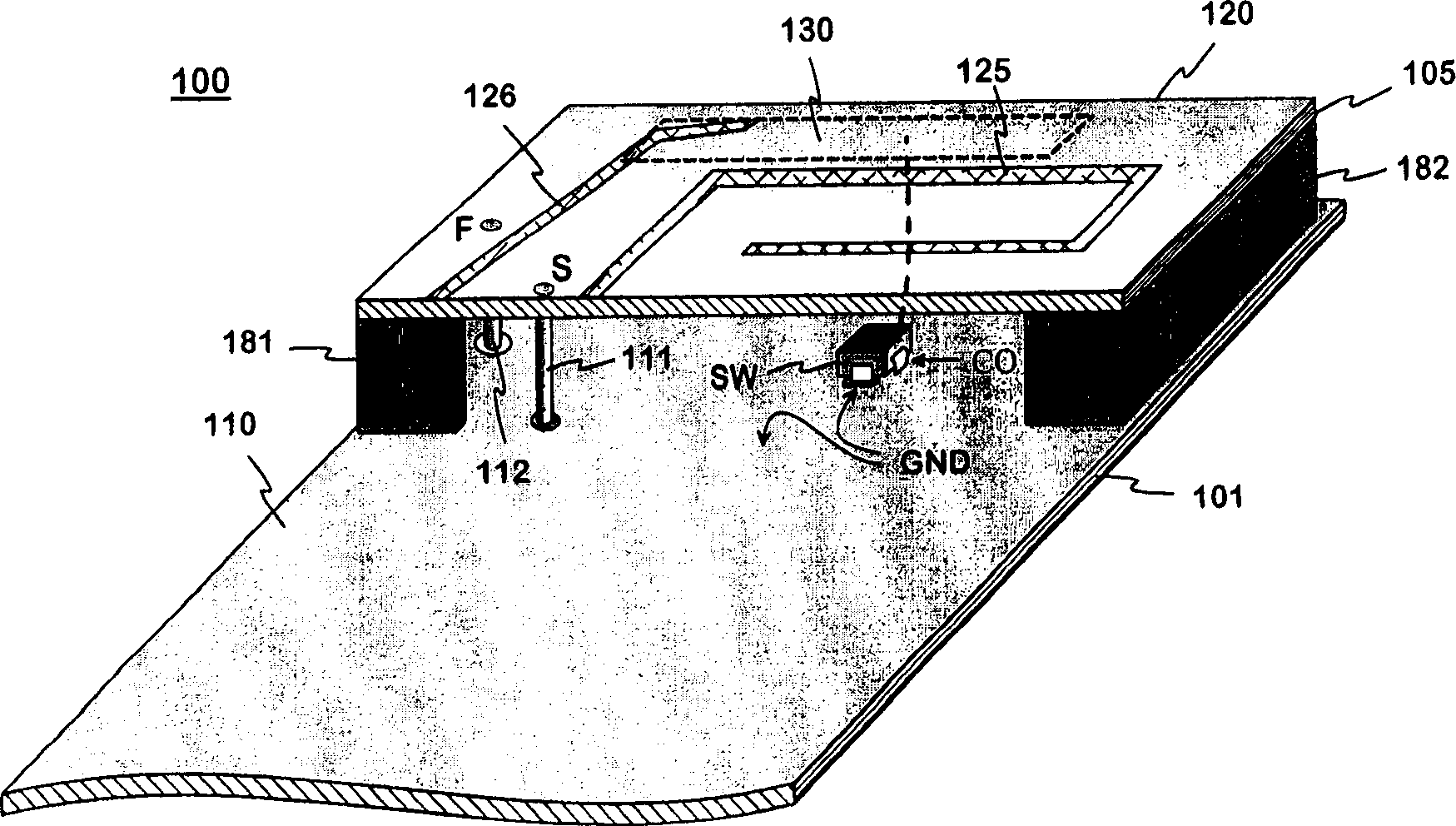
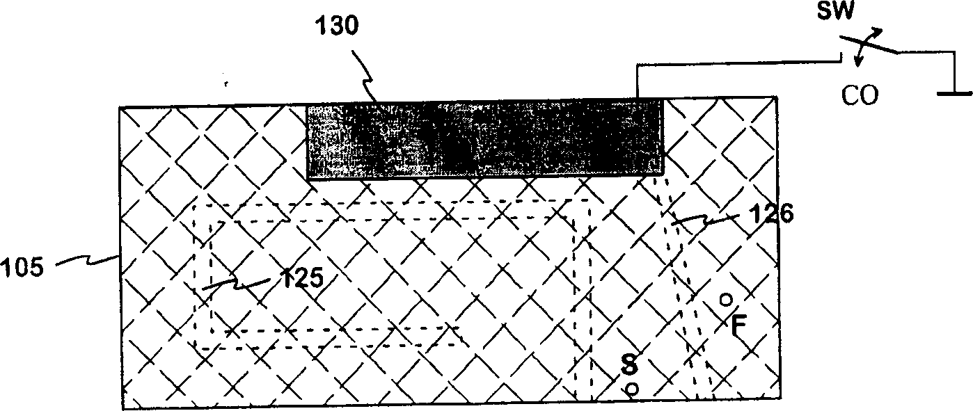
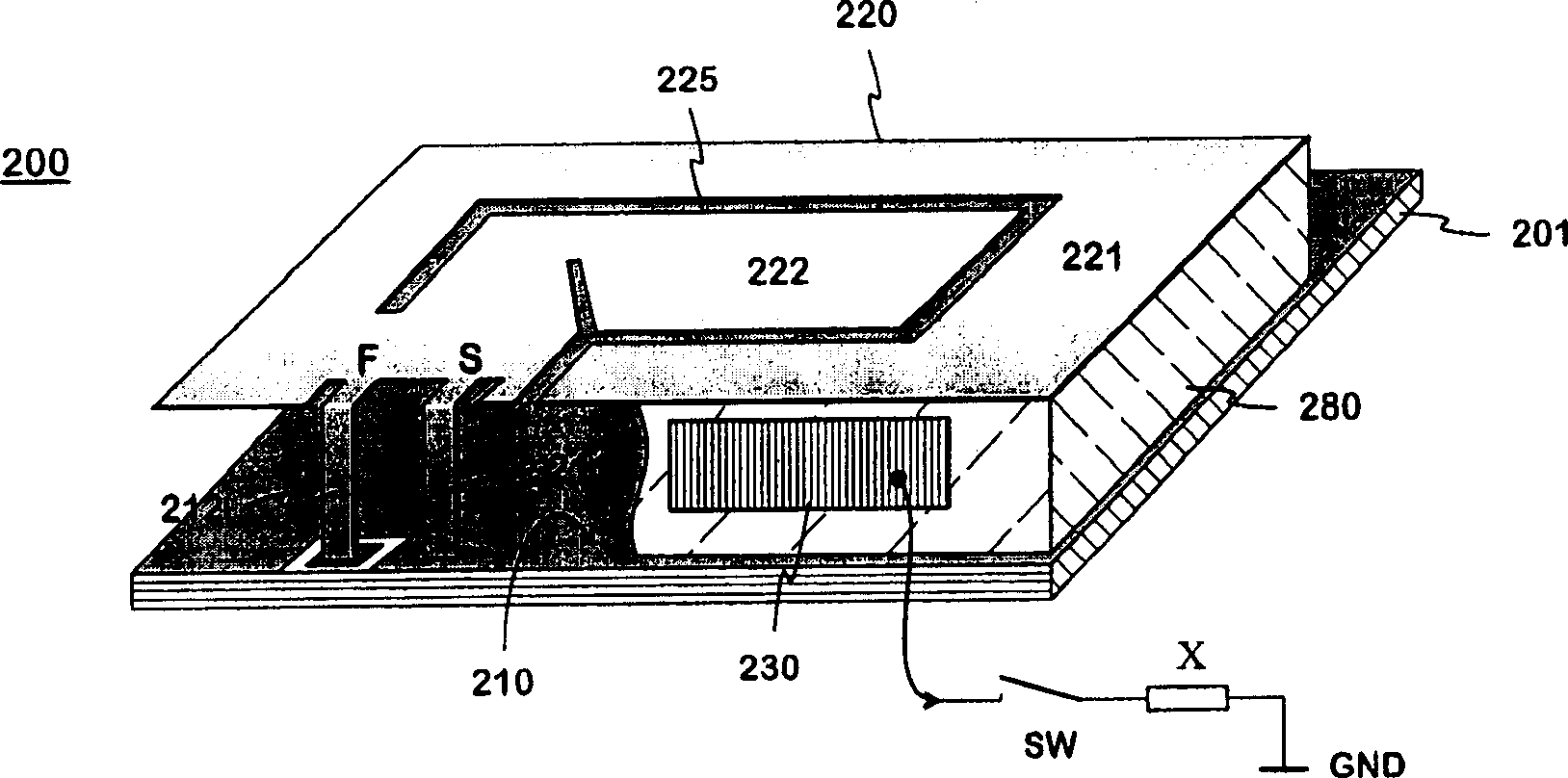
[0025] Figure 4A structure representing the principles of the invention is presented. Only a portion 422 of the radiating plane is demarcated from the antenna base structure. Besides the base structure, the antenna structure also includes a tuning circuit with a parasitic element 430, a filter 440, a switch SW and a terminating element TE. The parasitic element has significant electromagnetic coupling with the portion 422 of the radiating plane and is connected to the input port of the filter 440 through a short-circuited transmission line. The output port of the filter is connected to the bidirectional switch SW through the second short-circuit transmission line, and the "hot end" of the output port is connected to the first end of the switch SW. By controlling the switch, it is possible to connect the first terminal to either the second terminal or the third terminal of the switch SW. The second end is fixedly connected to one conductor 453 of the third short-circuit tran...


PUM


Abstract

An adjustable multi-band planar antenna especially applicable in mobile terminals. In the structure of the antenna, advantageously on a surface of a dielectric part, there is placed a conductive element (430) having a significant electromagnetic coupling to the radiating plane (422). The arrangement further comprises a filter (440) and a switch (SW) so that the parasitic conductive element at issue can be connected through the filter to a terminal element (TE) connected to the ground plane. That terminal element is pure short-circuit or a reactive element. An antenna's operation band, which is desired to be displaced, situates on pass band of the filter, and another operation band, which is desired not to be effected, situates in stop band of the filter. Controlling the switch causes the electric length of the antenna's part corresponding for example the upper operation band to change measured from the short-circuit point, in which case also the resonance frequency changes and the band is displaced. Only one operation band of the antenna is affected because on the other operation bands a high impedance is 'seen' from the parasitic element towards the ground, although the switch is closed.

Description

technical field [0001] The invention relates to an adjustable multi-band planar antenna, in particular to an adjustable multi-band planar antenna in a mobile terminal. The invention further relates to radio equipment equipped with such an antenna. Background technique [0002] Antenna tunability in this description means that the resonant frequency or frequency of the antenna can be changed electrically. The aim is that the operating frequency band of the antenna around the resonant frequency always covers the frequency range functionally expected at a certain time. There are different reasons for tunability. As portable radio equipment, like mobile terminals, is becoming smaller and thinner, the distance between the radiation plane and the ground plane of the internal planar antenna inevitably becomes shorter. The disadvantage of reducing said distance is that the bandwidth of the antenna is getting smaller. Then, as a mobile terminal is designed to function according t...

Claims


Application Information

Patent Timeline
Patent Type & Authority Applications(China)
IPC IPC(8): H01Q1/24H01Q5/10H01Q9/04H01Q21/30
CPCH01Q9/0442H01Q9/0421H01Q1/243H01Q21/30
Inventor Z·米洛萨夫列维奇
Owner L K PROD OY
Learn More