
Data transceiving method and device of coder

一种数据发送装置、数据接收装置的技术,应用在测量装置、采用电/磁装置传递传感构件、仪器等方向,能够解决驱动速度/计数分辨率制约、不能取得外部传感器的触发信号位置数据等问题,达到提高控制稳定性、高分辨率、提高可靠性的效果

Inactive Publication Date: 2004-10-27
MITUTOYO CORP
View PDF5 Cites 13 Cited by
  • Summary
  • Abstract
  • Description
  • Claims
  • Application Information

AI Technical Summary

Problems solved by technology

[0013] However, as mentioned above, due to the incremental pulse transmission method, there are restrictions on the driving speed / counting resolution
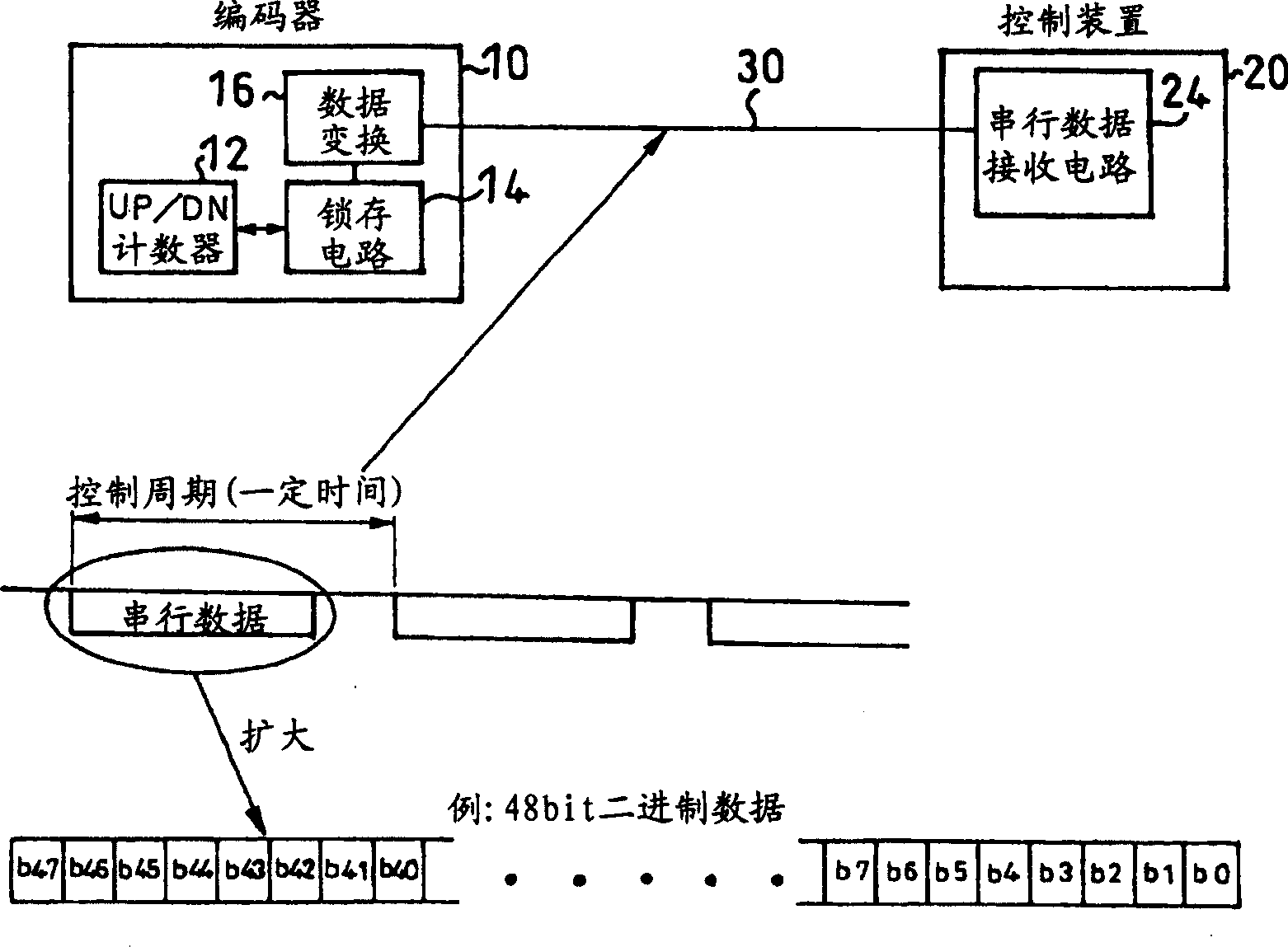
[0014] On the other hand, in the latter serial data transmission method, if it is a device that only controls the position and speed, there is no problem, but there is a problem that the trigger of the external sensor cannot be obtained except for the control data every fixed cycle. Issues with location data at the time of signal occurrence

Method used


Image

  • Data transceiving method and device of coder
  • Data transceiving method and device of coder
  • Data transceiving method and device of coder

Examples


Embodiment Construction

[0050] Embodiments of the present invention will be described in detail below with reference to the drawings.

[0051] In the first embodiment of the present invention, with figure 2 In the encoder 10 and the control device 20 of the same serial data transmission method as shown in the prior art, as Figure 5 As shown, a subtraction circuit 18 for positional data division is set in the encoder 10, and the positional data such as Figure 6 As shown in the time division (here is four divisions), such as Figure 7 As shown, the time-divided position data is output together with the deviation data output each time, and an adding circuit 27 for reconstructing (synthesizing) the position data is provided in the control device 20, and the serial data receiving circuit 24 receives the The position data is reconstructed and checked against the position calculated from the deviation data.

[0052] Specifically, if the control device 20 issues a transfer request every certain time pe...


PUM


Abstract

When data detected by an encoder is transmitted / received in predetermined cycles in a measuring device using a sampling control system for controlling a position or a speed at predetermined time intervals, positional data is divided so as to be output with deviation data output each time. The divided positional data are reconstituted so as to transmit the positional data within a control cycle.

Description

[0001] Published Japanese Patent Nos. 2003-118691 (applied April 23, 2003) and No. 2003-139987 (applied May 19, 2003), including their specification, drawings, and claims, are hereby incorporated by reference in their entirety quote. technical field [0002] The present invention relates to a data transmission and reception method and device for an encoder for transmitting and receiving data detected by the encoder at a predetermined cycle. In particular, the use of linear encoders or rotary encoders (hereinafter collectively referred to as encoders) suitable for control devices such as three-dimensional coordinate measuring machines, machine tools, image measuring devices, and shape measuring devices, to control position and speed at fixed time intervals In the measurement device of the sampling control system of the present invention, it relates to a data transmission and reception method and device of an encoder capable of transmitting position data within a control period....

Claims


Application Information

Patent Timeline
Patent Type & Authority Applications(China)
IPC IPC(8): G01D5/244
CPCG01D5/24428
Inventor 寺口干也冈本雅美
Owner MITUTOYO CORP
Learn More