Optical rotary coder

A rotary encoder and optical technology, applied in the direction of using optical devices, converting sensor output, instruments, etc., can solve the problems of small size, high resolution, dial image changes, and reducing the amount of detection light, etc., to suppress changes in illumination distribution , Reduce the detection error and ensure the effect of resolution

Active Publication Date: 2004-10-27
MITSUBISHI ELECTRIC CORP
View PDF5 Cites 16 Cited by
  • Summary
  • Abstract
  • Description
  • Claims
  • Application Information

AI Technical Summary

Problems solved by technology

That is, in order to achieve miniaturization and high resolution, even if the period of the optical pattern is narrowed within the boundary line, the size of the encoder itself still depends on the size of the photosensitive element group having twice the radial length of the optical pattern, and it cannot be realized Fully small, high-resolution
[0015] In addition, since the light beam reflected by the rotating dial and incident on the photodetector is not a parallel beam, when the distance between the photodetector and the rotating dial changes, since the irradiation distribution on the rotating dial changes greatly, the photosensitive Fluctuations in the amount of light detected by the element group cause detection errors
[0016] Furthermore, since the rotary dial is reflective, when the rotary dial is tilted, the image of the dial on the photosensitive element group fluctuates, and a detection error occurs.
[0017] In addition, the optical rotary encoder disclosed in Patent Document 3 has the following problems. Although the incident light from the light source to the rotary dial uses a parallel beam, since two positions in the rotary dial have The reflected light on the 45° inclined surface is irradiated on the optical pattern plate, so the distribution of irradiation on the optical pattern plate changes greatly according to the posture change of the rotation axis, resulting in detection errors. In addition, the width of the beam irradiated on the optical pattern plate is due to become Approximately 1 / 2 the diameter of the parallel beam incident on the rotating dial, thus limiting the formed optical pattern area
Therefore, when miniaturization is performed, since the amount of detection light is reduced, there is a limitation in high resolution, etc.

Method used


Image

  • Optical rotary coder
  • Optical rotary coder
  • Optical rotary coder

Examples


Embodiment Construction

[0038] Hereinafter, embodiments of the present invention will be described with reference to the drawings. In addition, in the specification of the present application, terms indicating directions (for example, "upper", "lower", "right", "left" and other terms including these terms) are used appropriately, but this is only for illustration. The directions in the drawings are used, and the invention should not be construed in a limited way by these terms.

[0039] Embodiment 1

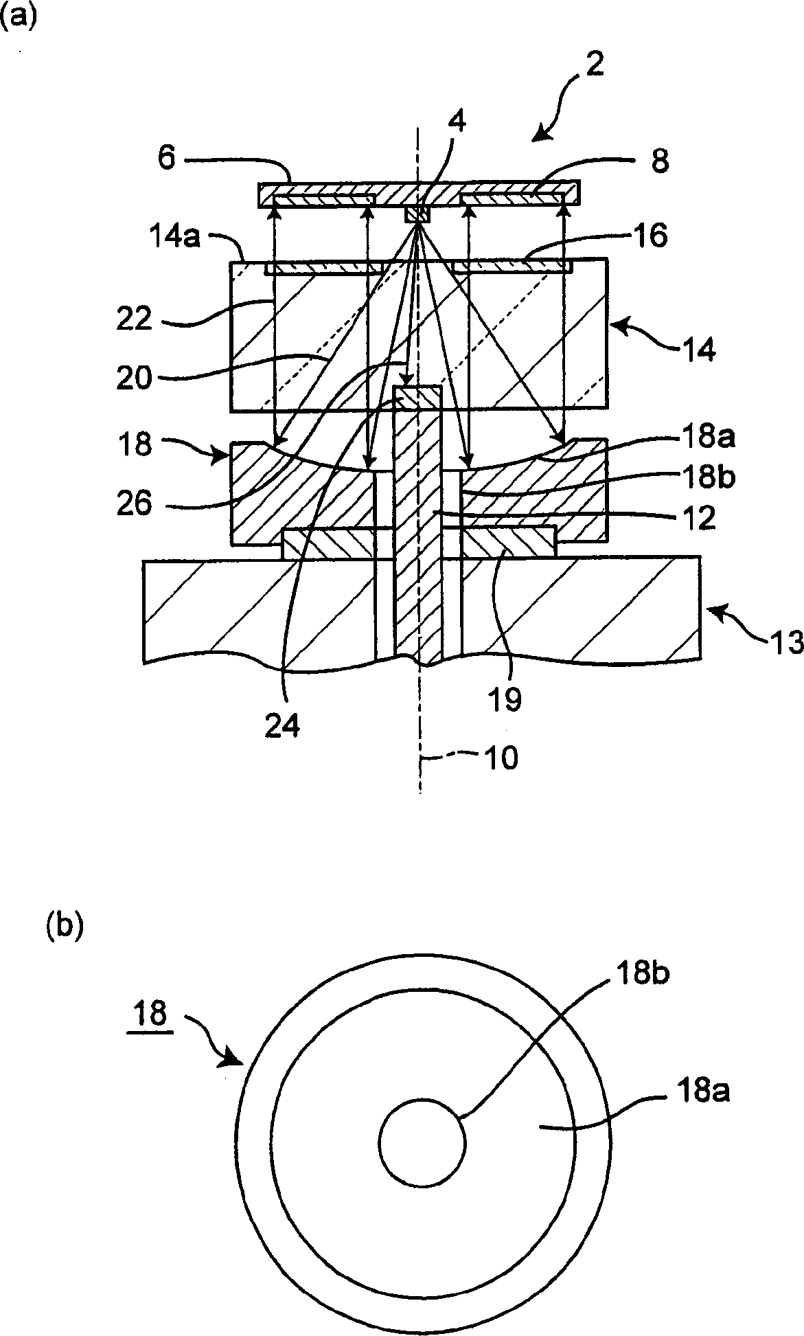
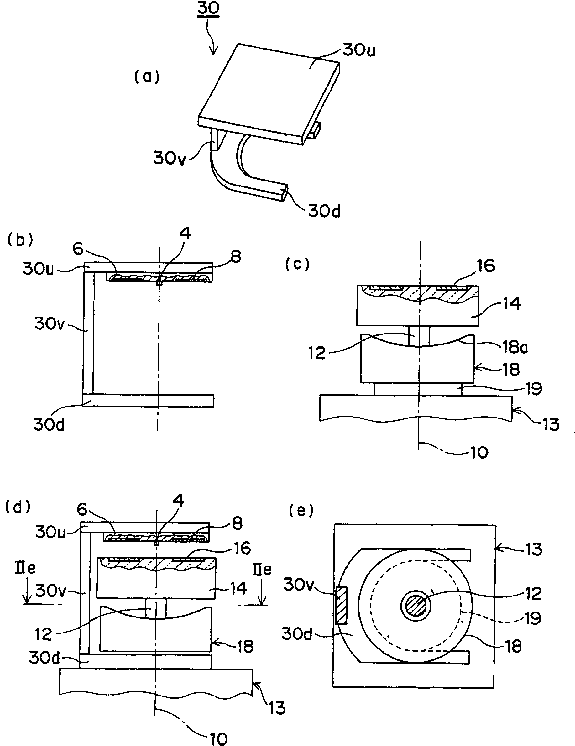
[0040] figure 1An optical rotary encoder according to Embodiment 1 of the present invention is shown. The overall encoder shown by reference numeral 2 includes a surface-emitting light source 4 mounted on a central portion of a substrate 6 , and a photosensitive element group 8 is formed integrally with the substrate 6 around it. The light source 4 is arranged on the extension line of the rotation center line 10 of the rotation shaft 12 of the equipment such as a motor 13, and the photosensitive elem...


PUM


Abstract

Provided is a small and high resolution optical rotary encoder which is unlikely to generate detection errors, even if a rotary scale is inclined at attitude fluctuation of the rotational shaft. The encoder 2 is provided with a light source 4, disposed near a rotation center line 10 of the rotational shaft 12, the rotary scale 14 attached to the rotational shaft, rotated about the rotational center line and having an optical pattern 16, comprising a light-transmitting part and a light-shielding part alternately formed in the circumferential direction; a reflection element 18 disposed and spaced from the rotary scale, reflecting and converting the light from the light source into a parallel light flux, prevented from a width change in a cross section including the rotational center line, irradiating the light transmitting part of the rotary scale with the parallel light flux and directing the light transmitted through the light transmitting part to the periphery of the light source; and a light-receiving element 8 for receiving the light transmitted through the light-transmitting part.

Description

technical field [0001] The present invention relates to an optical rotary encoder for detecting the rotation angle and speed of a rotary shaft. Background technique [0002] Among the optical rotary encoders, there is a surface-emission type in which a rotary dial provided with a reflective optical plate or a diffraction grating plate is arranged on a substantially extended line (rotation center line) of the rotary axis of the rotary dial. The light source is a device formed on a substrate on which the light source is mounted and has photodetector groups of photosensitive element groups arranged at predetermined angular intervals on a circumference centered on the light source (for example, refer to Patent Document 1). [0003] In addition, there is also a device in which photosensitive element groups are arranged around the entire circumference of the rotating dial on the side opposite to the light source with the center line of rotation as the center (for example, refer to...

Claims


Application Information

Patent Timeline
Patent Type & Authority Applications(China)
IPC IPC(8): G01D5/30G01D5/34G01D5/347
CPCG01D5/342G01D5/34715
Inventor 岡彻大村阳一
Owner MITSUBISHI ELECTRIC CORP
Why Eureka
Try Eureka