Driving device and vehicle with the driving device

A drive device and drive shaft technology, which is applied to transmission devices, power devices, electric power devices, etc., can solve problems such as the large number of components in the drive device, the inability to independently control the left and right wheels, and the inability to improve the responsiveness of hydraulic brakes.

Active Publication Date: 2015-11-25
HONDA MOTOR CO LTD
View PDF9 Cites 0 Cited by
  • Summary
  • Abstract
  • Description
  • Claims
  • Application Information

AI Technical Summary

Problems solved by technology

In addition, especially when starting immediately after the vehicle is started at a low temperature, since the oil temperature is low, the viscous resistance of the oil is large, and there is a problem that the responsiveness of the hydraulic brake 128 cannot be improved.
[0007] In addition, in the driving device 100 described in Patent Document 1, since one electric motor 102 is distributed to the left and right axles 110A, 110B of the vehicle through the differential device 113, the left and right wheels cannot be independently controlled.
Furthermore, if two electric motors capable of independently outputting driving force are provided on the left and right axles, there is a problem that the size of the driving device increases and the number of components increases.

Method used


Image

  • Driving device and vehicle with the driving device
  • Driving device and vehicle with the driving device
  • Driving device and vehicle with the driving device

Examples


no. 1 approach

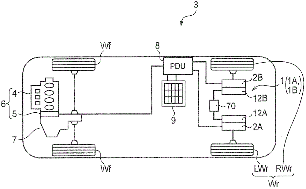
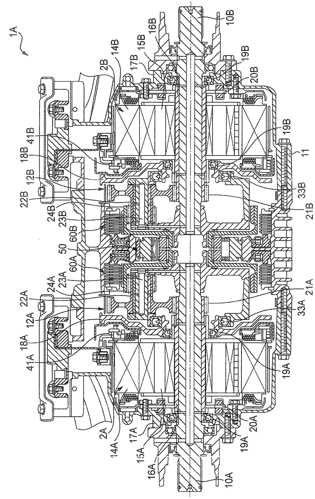
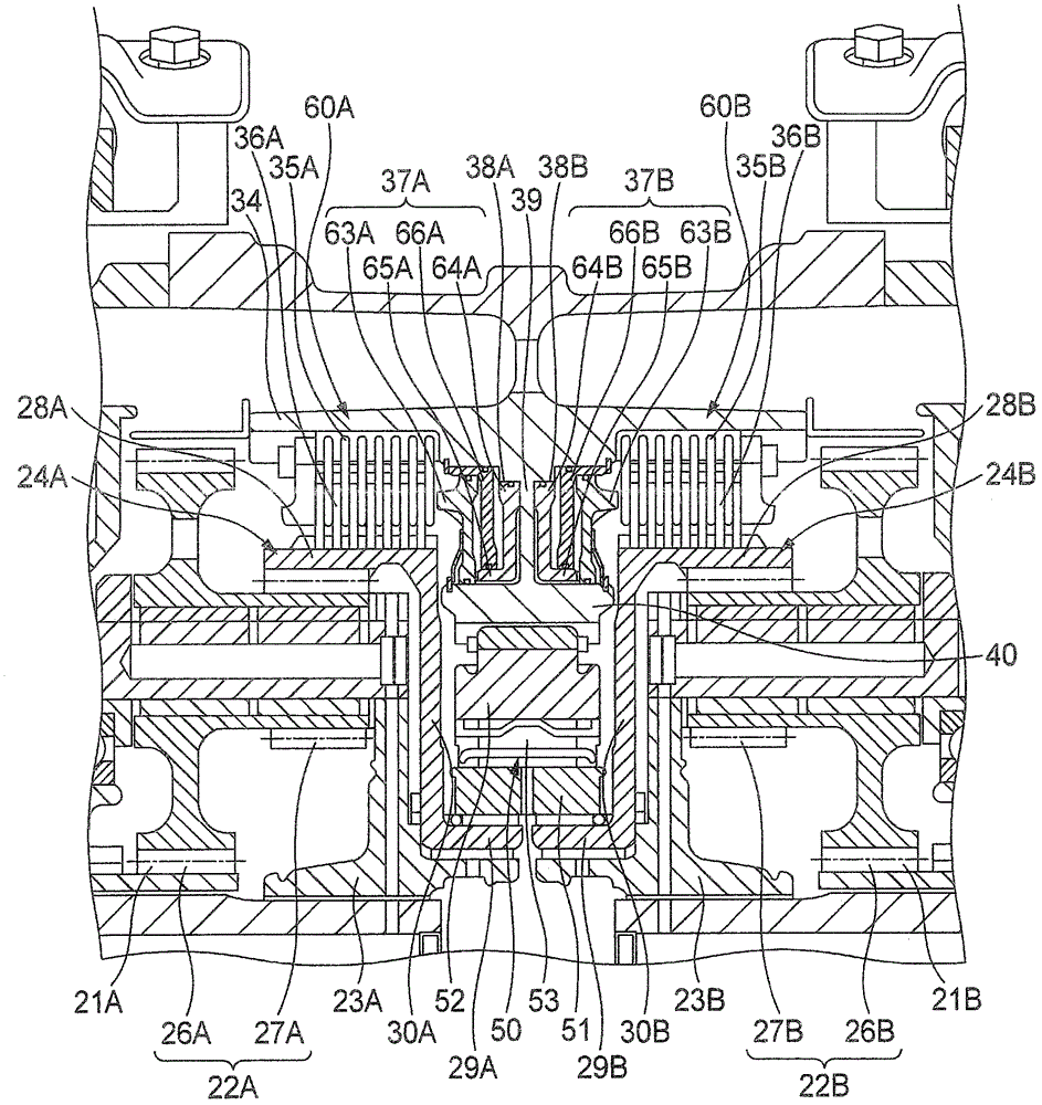
[0133] figure 2 It is a longitudinal cross-sectional view showing the whole of the driving device 1A according to the first embodiment. In this figure, 10A and 10B denote left and right axles on the rear wheel Wr side of the vehicle, and are coaxially arranged in the vehicle width direction. The speed reducer housing 11 of the driving device 1A is formed in a substantially cylindrical shape as a whole, and the motors 2A and 2B for driving the axles and the planetary gear speed reducers 12A and 12B for reducing the driving rotation of the motors 2A and 2B are arranged inside the speed reducer case 11. On the same axis as the axles 10A, 10B. The electric motor 2A and the planetary gear reducer 12A control the left rear wheel LWr, the electric motor 2B and the planetary gear reducer 12B control the right rear wheel RWr, and the electric motor 2A, the planetary gear reducer 12A, the electric motor 2B and the planetary gear The type speed reducer 12B is arranged in the speed redu...

no. 2 approach

[0145] Next refer to Figure 4 and Figure 5 A drive device according to a second embodiment of the present invention will be described. It should be noted that the driving device of the second embodiment has the same structure except for the arrangement of the driving device 1A, the hydraulic brake, and the one-way clutch of the first embodiment, so the same or equivalent parts are given the same or equivalent symbols. , and its description is omitted.

[0146] Figure 4 10A, 10B are left and right axles on the rear wheel Wr side of the vehicle, and are coaxially arranged in the vehicle width direction. The speed reducer housing 11 of the driving device 1B is formed in a substantially cylindrical shape as a whole, and the motors 2A and 2B for driving the axles and the planetary gear speed reducers 12A and 12B for reducing the driving rotation of the motors 2A and 2B are arranged inside. On the same axis as the axles 10A, 10B. The electric motor 2A and the planetary gear ...


PUM


Abstract

A drive device 1A includes: electric motors 2A and 2B that outputs drive powers; and planetary gear reducers 12A and 12B disposed between axles 10A and 10B connected to cylindrical shafts 16A and 16B serving as the output shafts of the electric motors 2A and 2B and to rear wheels LWr and RWr. The drive device 1A further includes: a one-way power transmission device that transmits the one-way rotation power of the electric motors 2A and 2B to the axles 10A and 10B; and a two-way power transmission device that transmits the two-way rotation power of the electric motors 2A and 2B to the axles 10A and 10B. The one-way power transmission device and the two-way power transmission device are disposed on transmission passages from the electric motors 2A and 2B to the axles 10A and 10B.

Description

technical field [0001] The invention relates to a drive device and a vehicle with the drive device. Background technique [0002] As a driving device for a vehicle, a proposal has been proposed in which the left and right axles of the vehicle are connected to a differential device, and a motor arranged coaxially on the outer periphery of one axle shaft transmits a driving force to the differential device via a reduction mechanism (for example, Refer to Patent Document 1). [0003] Such as Figure 16 As shown, the driving device 100 has an axle driving motor 102, a planetary gear reducer 112 for decelerating the driving rotation of the motor 102, and an output of the planetary gear reducer 112 distributed to the left and right axles 110A of the vehicle. In differential device 113 of 110B, planetary gear reducer 112 and electric motor 102 are arranged coaxially on the outer peripheral side of one axle 110B coupled to differential device 113 . Moreover, the sun gear 121 and t...

Claims


Application Information

Patent Timeline
Patent Type & Authority Patents(China)
IPC IPC(8): F16H1/28B60K6/365B60K6/383B60K6/40B60K6/44F16H48/30B60L50/16B60W30/18
CPCB60K1/02B60K1/00B60K6/383B60K6/442B60K6/52B60K7/0007B60K17/046B60K17/26B60K2007/0046B60K2007/0092B60W10/02B60W10/08B60W10/10B60W10/196B60W20/00B60W30/18009Y02T10/6234Y02T10/6265Y10T477/322B60Y2400/427Y02T10/62B60W10/16B60W10/18B60W20/13B60W10/115
Inventor 吉良畅博大碕桂一星野谷武森田英树小野浩一
Owner HONDA MOTOR CO LTD
Why Eureka
Try Eureka