Printing device and its control method and consumpable device mounted on same

A technology of printing equipment and consumption unit, which is applied in the directions of digital output to printing unit, equipment of electric recording process applying charge pattern, electric recording process applying electric charge pattern, etc., which can solve the problems of increasing system cost and the like

Inactive Publication Date: 2004-10-27
CANON KK
View PDF1 Cites 7 Cited by
  • Summary
  • Abstract
  • Description
  • Claims
  • Application Information

AI Technical Summary

Problems solved by technology

[0013] However, the method of storing data important to the control of the print engine (for example, data related to the service life of the process cartridge) at a plurality of addresses requires a large capacity of the nonvolatile memory and leads to an increase in the cost of the system

Method used


Image

  • Printing device and its control method and consumpable device mounted on same
  • Printing device and its control method and consumpable device mounted on same
  • Printing device and its control method and consumpable device mounted on same

Examples


no. 1 example

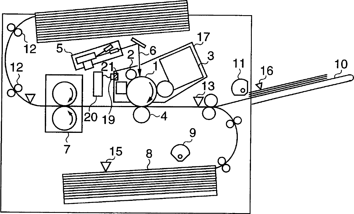
[0034] FIG. 1 is a sectional view showing the structure of a printing apparatus according to an embodiment of the present invention.

[0035] The same reference numerals in FIG. 1 as those in the aforementioned FIG. 9 denote substantially the same parts, and the respective constituent parts are as follows.

[0036]Reference numeral 1 denotes a photosensitive drum for forming an electrostatic latent image; 2, a charging roller for uniformly charging the photosensitive drum 1; 5, an optical unit for scanning the surface of the photosensitive drum 1 with a laser beam; A laser beam emitted from the optical unit 5; 3 denotes a developer for developing an electrostatic latent image formed on the photosensitive drum 1 with toner; 4 denotes a device for transferring the toner image on the photosensitive drum 1 to a A transfer roller charger on predetermined paper; 7 denotes a fuser for melting and fixing the toner to the paper; 8 denotes a standard paper tray for storing a stack of pa...

no. 2 example

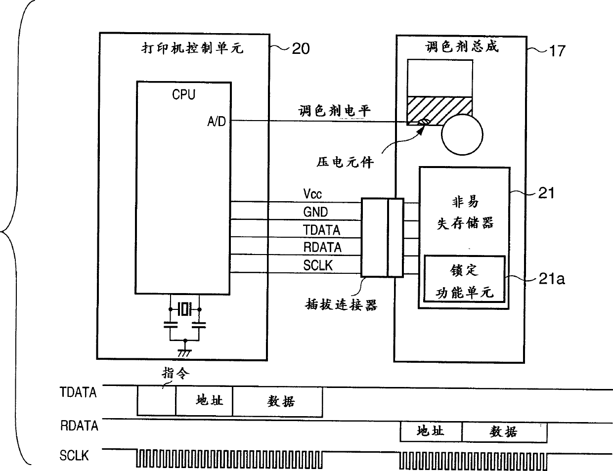
[0064] The second embodiment will describe a case where a wireless communication function is employed between the nonvolatile memory 21 and the printer control unit 20 .

[0065] FIG. 6 shows the interface between the printer control unit 20 and the wireless storage.

[0066] Toner level detection is performed in the same manner as in the first embodiment.

[0067] In the second embodiment, the interface between the non-volatile memory 21 and the printer control unit 20 has a wireless setting, ie no electrical contact. Therefore, the read / write driver circuit 20a is built in the printer control unit 20, and it is connected to the coil antenna 20b. The process cartridge has a coil-shaped antenna 21b connected to the nonvolatile memory 21 and positioned opposite to the antenna 20b when mounted on the printer. Communication is established by electromagnetic coupling between antennas 20b and 21b.

[0068] In principle, electric power is generated in the coil 21b connected to th...

no. 3 example

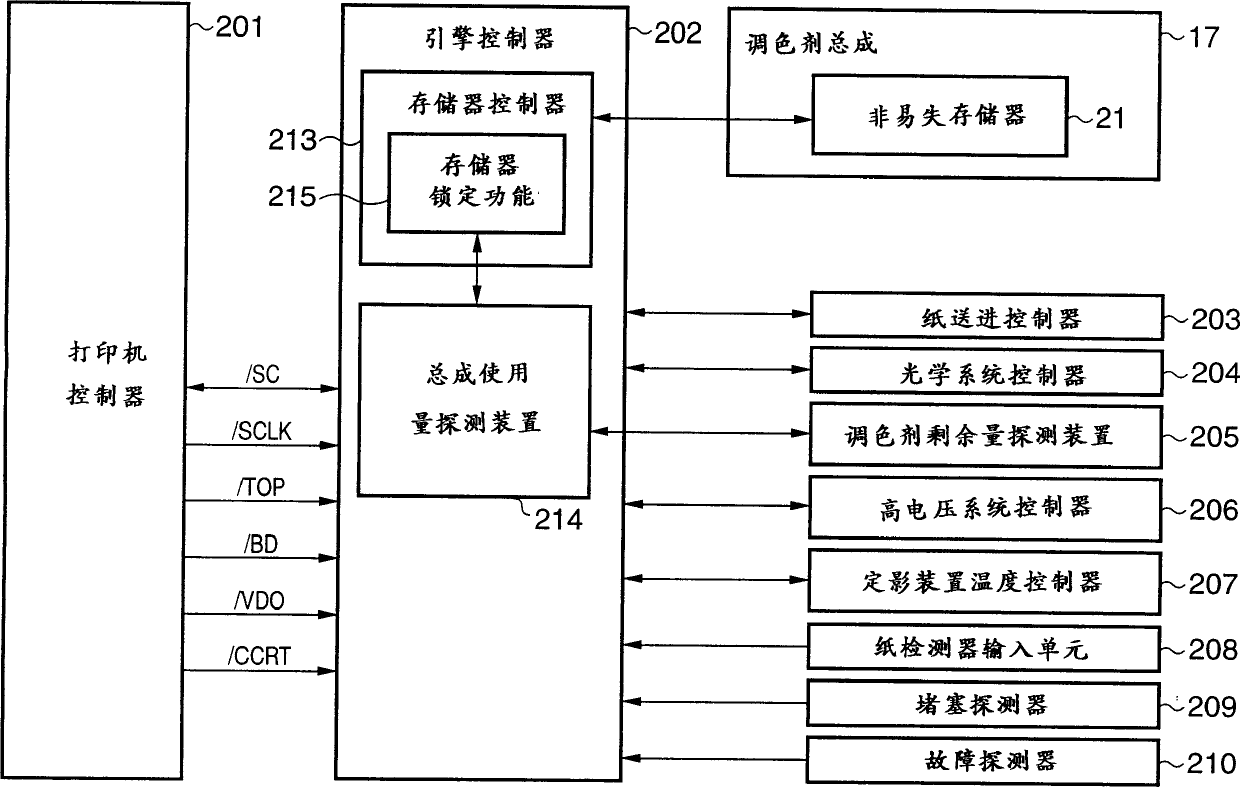
[0072] The third embodiment will describe a case in which the memory lock setting for prohibiting rewriting of the memory is made based on an instruction from the printer controller instead of a determination by the engine controller.

[0073] Fig. 7 is a block diagram showing the interface between the engine controller and the printer controller and the memory.

[0074] Referring to FIG. 7, reference numeral 301 denotes a printer controller for receiving image data through communication with a host computer, converting the received image data into information that the printer can print, and communicating with the printer engine controller ( will be described later) exchange signals. The printer controller 301 has a function of displaying a message on a display panel when it is judged from the content of the serial communication from the engine controller that the usage amount of the toner process cartridge has exceeded a predetermined value, thereby notifying the user that th...


PUM


Abstract

This invention provides a printing apparatus which controls to inhibit any inadvertent write to a memory in an expendable so as to securely manage the exchange timing and the like of the expendable. For this purpose, the expendable such as a toner cartridge or the like comprises a rewritable nonvolatile memory (21) which holds information indicating whether or not its service life has expired. When the toner cartridge is attached to the printing apparatus, it is ready to communicate with a printer engine controller in the printing apparatus, and write to the nonvolatile memory (21) can be made in accordance with an instruction from a control unit. A lock functional unit (21a) writes information indicating write inhibition at a predetermined address in the nonvolatile memory (21), thus inhibiting write to the address position that stores the information indicating whether or not its service life has expired.

Description

[0001] This application is a divisional application of a patent application with application number 00129281.1, titled "Printing Device, Its Control Method, and Consumable Device Installed Thereon". technical field [0002] The present invention relates to a printing apparatus and its control method, and a consumable device attached to the printing apparatus and having a memory. Background technique [0003] Fig. 9 shows the arrangement of a conventional electrophotographic apparatus as an example of such a printing apparatus. [0004] Referring to FIG. 9, reference numeral 1 denotes a photosensitive drum for forming an electrostatic latent image; 2 denotes a charging roller for uniformly charging the photosensitive drum 1; 5 denotes an operation unit for generating a laser beam which scans the The surface of the photosensitive drum 1; 6 denotes a laser beam emitted from the optical unit 5; 3 denotes a developer for developing an electrostatic latent image formed on the phot...

Claims


Application Information

Patent Timeline
Patent Type & Authority Applications(China)
IPC IPC(8): G03G21/00G03G15/00G03G21/18G06F3/12
CPCG03G15/556G03G15/553G03G2215/0888G03G2221/1823G03G21/1889G03G15/5079G03G21/00
Inventor 芹泽洋司
Owner CANON KK
Why Eureka
Try Eureka