
Device of provding variable current for charged battery and method

A battery charging and charging current technology, applied in battery circuit devices, circuit devices, current collectors, etc., can solve problems such as transistor or field effect transistor damage, transistor damage, etc.

Inactive Publication Date: 2004-10-27
INSPUR LG DIGITAL MOBILE COMMUNICATIONS CO LTD
View PDF0 Cites 14 Cited by
  • Summary
  • Abstract
  • Description
  • Claims
  • Application Information

AI Technical Summary

Problems solved by technology

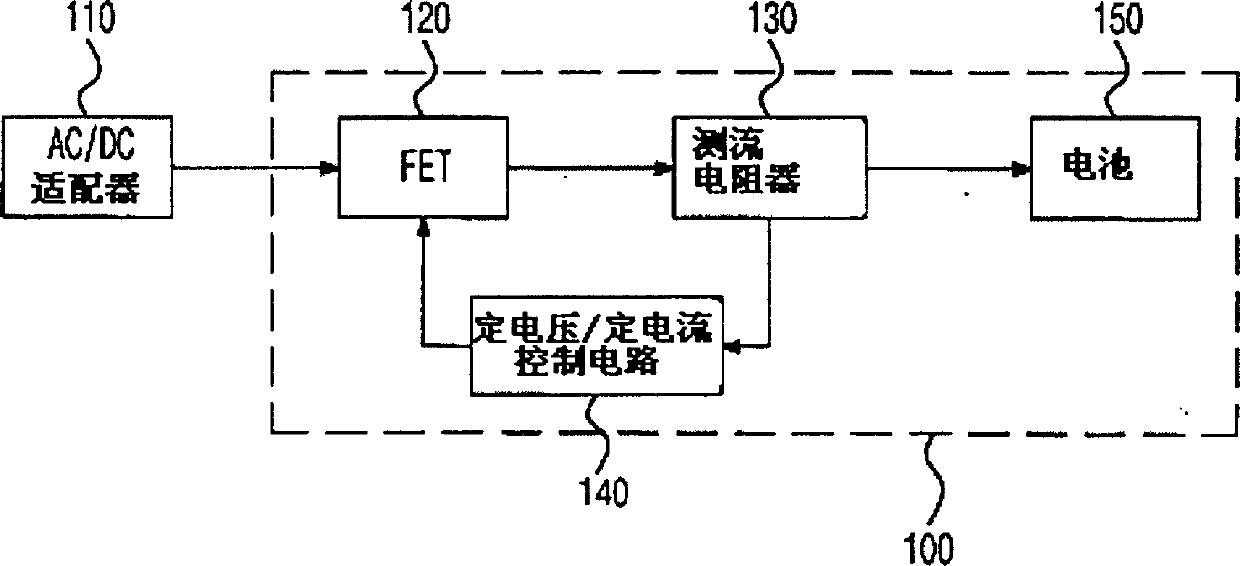
[0009] In this process, if the high voltage of the adapter (110) affects the power dissipation (Power dissipation) of the transistor or field effect transistor (120), then the transistor or field effect transistor may be damaged due to overheating
[0010] For example, if the power loss of the transistor is 1 watt (W), the voltage of the adapter is 6 volts, the battery voltage is 3 volts, and the charging current is 1 amp (A), then the actual power loss borne by the transistor is 3 watts, reaching 1 watt 3 times of , so the transistor is damaged due to overheating

Method used


Image

  • Device of provding variable current for charged battery and method
  • Device of provding variable current for charged battery and method
  • Device of provding variable current for charged battery and method

Examples


Embodiment Construction

[0023] Beneficial embodiments of the present invention will be described in detail below with reference to the accompanying drawings.

[0024] Fig. 2 is a schematic diagram of a general configuration diagram of a mobile communication system to which the present invention is applied.

[0025] The mobile communication system consists of a mobile communication terminal (210) (211) for sending and receiving credit, a plurality of base stations (220a) (220b)...(220n), a plurality of base station controllers (230a) (230b)...(230n) for controlling the base stations, and a switch Bureau (240) constitutes.

[0026] The effect of above-mentioned multiple base stations (220a) (220b)...(220n) is to convert the signal format between the mobile communication terminal (210) (211) and the switching office (240) of sending and receiving credit, so that it can access the wireless link and wired link. It measures the transmitting and receiving electric field intensity (radio wave receiving int...


PUM


Abstract

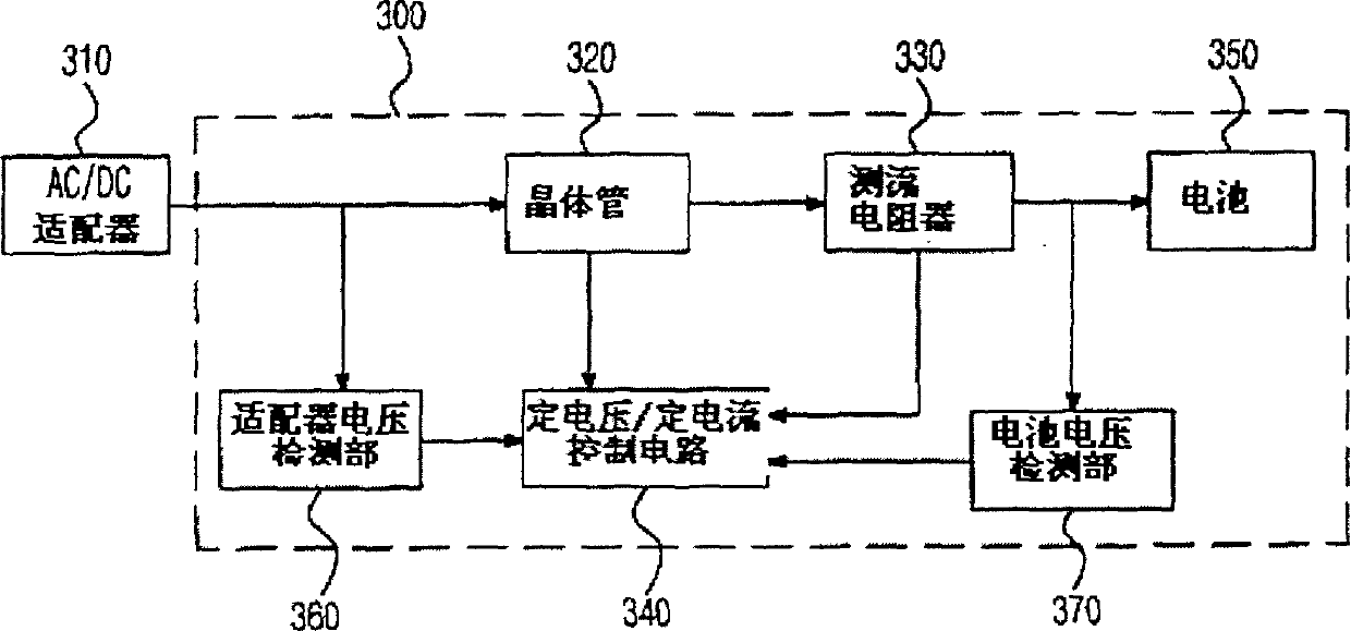
The invention includes following parts: adapter voltage detection unit, battery voltage detection unit and constant voltage / constant current control circuit. The adapter voltage detection unit is utilized to measure output voltage of adapter, and battery voltage detection unit is for measuring charged voltage of chargeable battery. The constant voltage / constant current control circuit compares magnitudes between measured output voltage of adapter and charged voltage of chargeable battery. If voltage difference between the said output voltage of adapter and charged voltage of chargeable battery is too large, the charging current is controlled in order to meet power consumption of transistor. The invention prevents overheating phenomenon in charging battery and damages of fittings.

Description

technical field [0001] The invention relates to a device and method capable of changing the charging current of a battery, especially a battery capable of measuring the output voltage of a mobile communication terminal adapter and the battery voltage, and changing the charging current of the battery according to the difference between the two voltages to minimize heat generation Charging current variable device and method thereof. Background technique [0002] Generally speaking, portable electronic devices use batteries as the power supply source required for work. Batteries use electrochemical reactions to convert the chemical energy of internal active substances into electrical energy. It plays a decisive role in creating the information age. From toys to high-end Cutting-edge products, batteries are integral to all portable electronics. [0003] However, due to the limitation of the service time of the battery, the use of portable electronic products is subject to many ...

Claims


Application Information

Patent Timeline
IPC IPC(8): H02J7/04H02J7/00
Inventor 金相友
Owner INSPUR LG DIGITAL MOBILE COMMUNICATIONS CO LTD
Learn More