Circuit for recovering timing data and implementing method

A clock data recovery and circuit technology, applied in the direction of electrical components, digital transmission systems, transmission systems, etc., can solve the problems of different implementation methods, poor anti-jitter ability, etc.

Inactive Publication Date: 2004-10-27
SANECHIPS TECH CO LTD
View PDF0 Cites 17 Cited by
  • Summary
  • Abstract
  • Description
  • Claims
  • Application Information

AI Technical Summary

Problems solved by technology

Because analog circuits are usually difficult to verify in pure digital system circuits, many systems have gradually begun to use pure digital phase-locked loops to achieve clock data recovery. Howe

Method used


Image

  • Circuit for recovering timing data and implementing method
  • Circuit for recovering timing data and implementing method
  • Circuit for recovering timing data and implementing method

Examples


Embodiment Construction

[0024] The present invention will be described in further detail below in conjunction with the accompanying drawings.

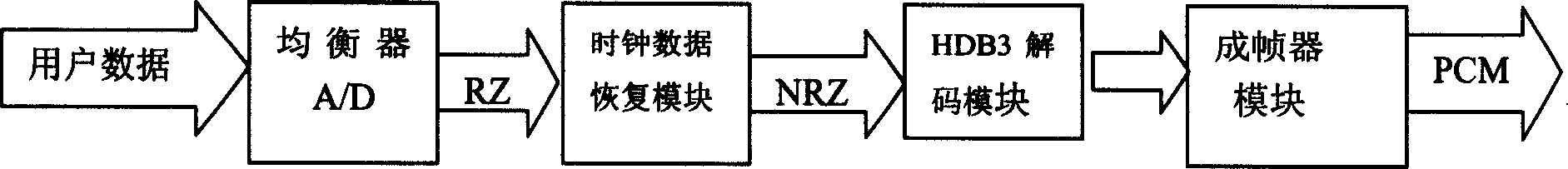
[0025] figure 1 The position of the clock data recovery module in the whole data processing system is described. The position of the clock data recovery module in the E1 system can be seen from the attached figure. The user data is outputted to the clock data recovery module after the balanced analog-to-digital conversion. The RZ signal recovers the system clock RCLK of the entire module after passing through the clock data recovery circuit. and the data NRZ signal to be further processed.

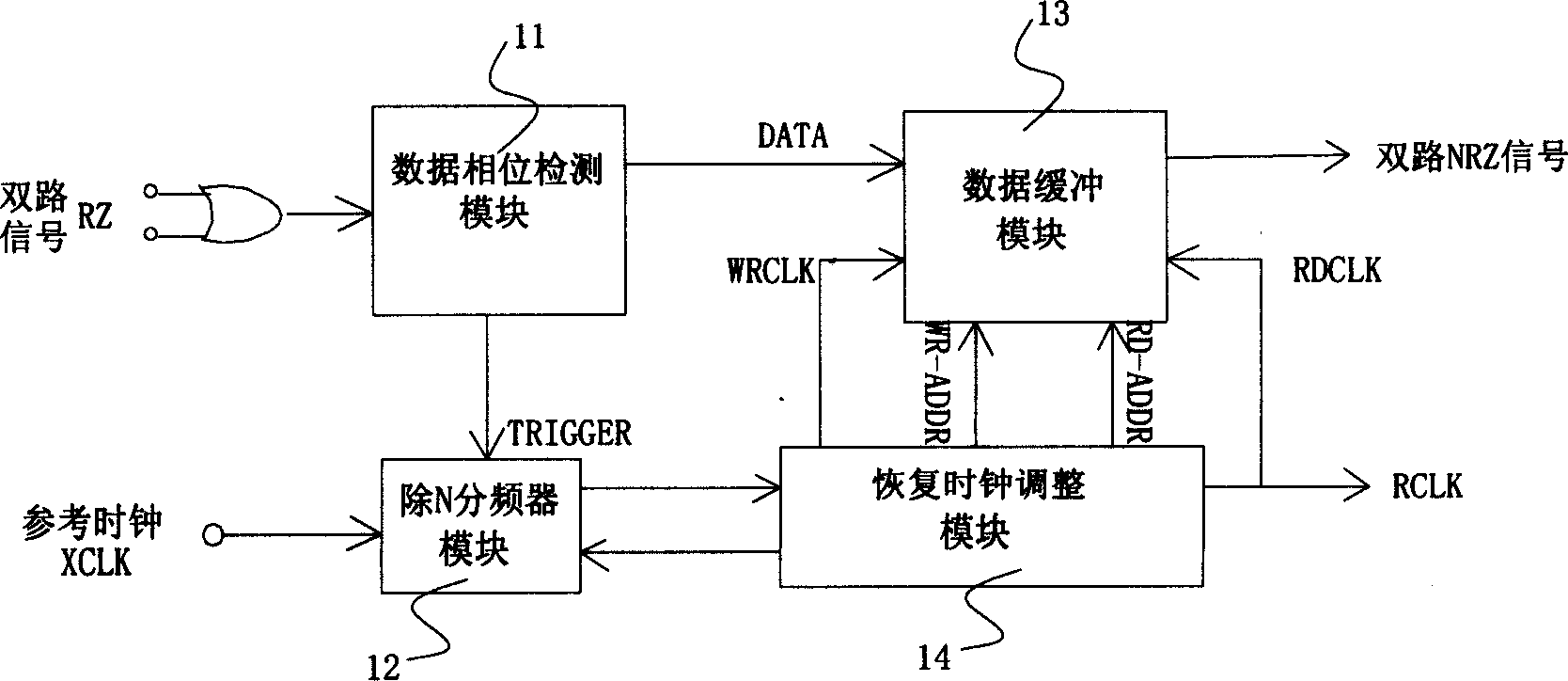
[0026] image 3 It is a system structure diagram of the clock data recovery circuit of the present invention. It includes four parts: data detection module 11 , N frequency division counter module 12 , data buffer module 13 and clock adjustment module 14 . In order to improve the sensitivity of the clock adjustment, smooth the small clock jitter, and recover the 2.04...


PUM


Abstract

The timing recovering circuit includes module of detecting data phase, frequency division module of dividing N, data buffering module and module of adjusting recovery timing. Recovery of timing data is carried out for RZ signal through buffering technique of processing data effectively so that recovery timing can be locked rapidly. The invention features removing dithering, and is applicable to recover timing data in procedure of synchronous data transmission.

Description

technical field [0001] The invention relates to a clock data recovery circuit and its realization method, in particular to a clock data recovery circuit and its realization method in E1 data processing in the field of narrowband communication. Background technique [0002] In the field of communication, in order to transmit data synchronously, the clock is usually hidden in the user data. Since the user data has a lot of jitter after being interfered by various external signals, before entering the E1 data processing system, ensure that The stability of the data is very important, so the clock data recovery circuit is widely used in the E1 data processing system in the communication field to ensure the stability of the clock data. [0003] At present, the clock data recovery circuit is usually realized by a digital-analog hybrid circuit. After the user data is converted from analog to digital, the user data and clock are extracted and recovered through the phase-locked loop...

Claims


Application Information

Patent Timeline
IPC IPC(8): H04L7/02
Inventor 邱敬涛李建宇
Owner SANECHIPS TECH CO LTD
Why Eureka
Try Eureka