Indoor arrangement for window type air conditioner

A technology for indoor air conditioners, applied in air conditioning systems, heating methods, space heating and ventilation, etc., can solve the problems of increased weight of air conditioners, unstable installation status, and many heat insulation measures, and achieve the minimum flow loss simplification, design simplification, and the effect of preventing air leakage

Inactive Publication Date: 2004-11-03
LG ELECTRONICS (TIANJIN) APPLIANCES CO LTD
View PDF0 Cites 2 Cited by
  • Summary
  • Abstract
  • Description
  • Claims
  • Application Information

AI Technical Summary

Problems solved by technology

However, in the above case, the weight of the air conditioner is increased; moreover, it also causes a problem of heat insulation between the indoor side and the outdoor side, and it is necessary to use parts such as a separate heat insulating board 9, resulting in an increase in the number of parts.
[0020] In addition, in the prior art, since the structure for operating the air conditioner is provided between the suction portion 5i of the front panel 5 and the discharge through hole 5c, air is sucked from the air-conditioning space through the suction portion 5i, and then the suction The air in the air conditioner is heat exchanged inside the air conditioner, and the air flow path that is discharged into the air conditioning space through the above-mentioned discharge through hole 5c is relatively long.
Therefore, it will lead to the problem of a lot of flow loss
[0021] In addition, since the above-mentioned control device 20 is arranged inside the air conditioner corresponding to the space between the above-mentioned indoor heat exchanger 11 and the casing 3, there is a problem that many parts need to be thermally insulated on the above-mentioned control device 20; and The above-mentioned control device 20 is installed on the upper end of the above-mentioned indoor heat exchanger 11, and the problem of unstable installation state will also occur.

Method used


Image

  • Indoor arrangement for window type air conditioner
  • Indoor arrangement for window type air conditioner
  • Indoor arrangement for window type air conditioner

Examples


Embodiment Construction

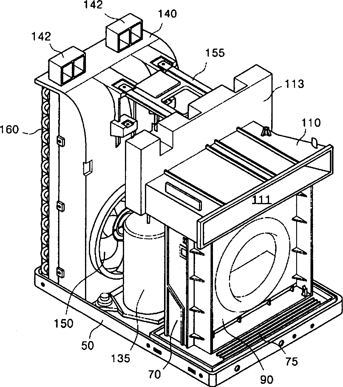
[0062] Hereinafter, referring to the accompanying drawings, an embodiment of the indoor structure of the window air conditioner of the present invention will be described in detail.

[0063] image 3 It is a perspective view showing the structure of the air conditioner according to the embodiment of the present invention without the casing, the front panel and the indoor heat exchanger. Figure 4 A perspective view showing the structure of the discharge guide rail constituting the embodiment of the present invention. Figure 5 It shows the state diagram of the fixed combination of the outdoor heat exchanger and the wind deflector in the present invention. Image 6 A sectional view showing the combination of the discharge guide rail and the control device in the embodiment of the present invention.

[0064] As shown in the figure, in the window type air conditioner of the present invention, the chassis 50 forms the bottom surface of the air conditioner. Various components co...


PUM


Abstract

The present invention is indoor assembly structure for one window type air conditioner with height/width ratio greater than 1. The space inside casing of the air conditioner is divided into indoor part and outdoor part with hollow track with air flow space and exhaust track combined to the upper end of the hollow track. The exhaust track is assembled to the hollow track via inserted slot and assembling rib in the hollow track and the inserting lug and inserted slot in the exhaust track. The exhaust track is also provided with setting guide, support rib and combining rib for installing the controller between the exhaust track and the casing, and has exhaust flow channel communicated with the through hole in the front panel of the air conditioner.

Description

[0001] technology area [0002] The present invention relates to a window type air conditioner; furthermore, it relates to an indoor side structure (INTRRIOR PARTS STRUCTURE OFCASEMENT WINDOW TYPE AIRCONDITIONER) of a window type air conditioner whose height is larger than the left and right width when viewed from the front. Background technique [0003] The window air conditioner is a machine in which all structural elements are arranged in a casing, and the window air conditioner is integrally arranged in a window for use. Window air conditioners are divided into different types according to the shape of the window. For example, the height of a window air conditioner used for opening and closing windows is larger than the left and right width when viewed from the front. Refer below figure 1 , the structure of a window air conditioner mainly used for opening and closing windows will be described. [0004] figure 1 An exploded oblique view showing the structure of a prior ...

Claims


Application Information

Patent Timeline
Patent Type & Authority Applications(China)
IPC IPC(8): F24F1/02
Inventor 张宇圣
Owner LG ELECTRONICS (TIANJIN) APPLIANCES CO LTD
Why Eureka
Try Eureka